Novel power system automatic scheduling device

A technology of power system dispatching and automation device, applied in terminal battery switching device and other directions, can solve problems such as damage to electrical equipment, increase in use cost, and difficulty in operation, and achieve safe and stable power supply, labor-saving dispatching operation, and low production input cost. Effect

Inactive Publication Date: 2018-07-06
何水明
View PDF0 Cites 0 Cited by
  • Summary
  • Abstract
  • Description
  • Claims
  • Application Information

AI Technical Summary

Problems solved by technology

[0002] Nowadays, our country is still a big country with scarce power resources, especially during the peak period of electricity consumption in summer, power outages often occur. Therefore, people usually store temporary power supply devices at home to provide power for electrical equipment at home during power outages. In use, the existing temporary power supply devices are basically based on batteries. When the electricity in one battery is used up, it is necessary to manually operate the electrical equipment to connect to another battery, so as to ensure the normal use of the electrical equipment, which is not only time-consuming and laborious , the operation is difficult, and only in the case of a sudden power failure of the electrical equipment can we know that the power in the battery has been used up, so it is easy to cause damage to the electrical equipment, making the power supply unstable, and it is necessary to store multiple batteries at home. Greatly increased the cost of use

Method used


Image

  • Novel power system automatic scheduling device
  • Novel power system automatic scheduling device
  • Novel power system automatic scheduling device

Examples


Embodiment Construction

[0021] The preferred embodiments of the present invention will be described in detail below in conjunction with the accompanying drawings, so that the advantages and features of the present invention can be more easily understood by those skilled in the art, so as to define the protection scope of the present invention more clearly.

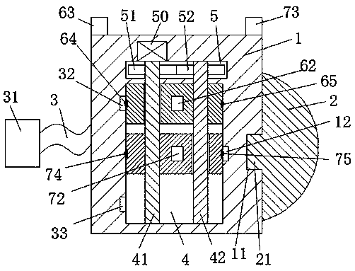
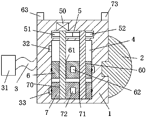
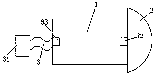
[0022] refer to Figure 1-4 A new type of power system scheduling automation device shown includes a housing 1 and an electrical device 2 detachably connected to the right end of the housing. The left end of the housing 1 is provided with a power cord 3, and the left end of the power cord 3 is A charging head 31 is connected, and the right end of the housing 1 is provided with a power supply slot 11, and the power supply slot 11 is used to cooperate with the power connection head 21 of the electric device 2 to make the electric device 2 energized. A left indicator light 63 and a right indicator light 73 are symmetrically arranged on the top surfa...


PUM


Abstract

The invention discloses a novel power system automatic scheduling device which comprises a shell and a power consumption device detachably connected at the right end of the shell. A power line is arranged at the left end of the shell. The left end of the power line is connected with a charging head. A power supply groove is formed in the right end of the shell. The power supply groove is used forbeing matched and connected with a power-on head of the power consumption device so that the power consumption device can be powered on. A left indicator lamp and a right indicator lamp are arranged on the top end face of the shell in a left-right symmetry mode. A scheduling cavity is formed in the shell. A gear cavity above the scheduling cavity is formed in the shell. The novel power system automatic scheduling device is simple in structure, convenient and rapid to operate and control and low in production input cost; an upper storage battery group and a lower storage battery group can be driven by a motor to be switched and scheduled when supplying power to the power consumption device, labor is saved during scheduling operations, the power supply of the power supply groove is safe andstable, the automatic scheduling of a power supply system is realized, and the use requirements in existing life are greatly met.

Description

technical field [0001] The invention relates to the field of electric power supply, in particular to a novel power system scheduling automation device. Background technique [0002] Nowadays, our country is still a big country with scarce power resources, especially during the peak period of electricity consumption in summer, power outages often occur. Therefore, people usually store temporary power supply devices at home to provide power for electrical equipment at home during power outages. In use, the existing temporary power supply devices are basically based on batteries. When the electricity in one battery is used up, it is necessary to manually operate the electrical equipment to connect to another battery, so as to ensure the normal use of the electrical equipment, which is not only time-consuming and laborious , the operation is difficult, and only in the case of a sudden power failure of the electrical equipment can we know that the power in the battery has been us...

Claims


Application Information

Patent Timeline
Patent Type & Authority Applications(China)
IPC IPC(8): H02J7/36
CPCH02J7/36
Inventor 何水明
Owner 何水明
Why Eureka
Try Eureka