Supercharge Your Innovation With Domain-Expert AI Agents!

Video signal adjustment device, and video signal adjustment method

A technology of video signal and gear signal, which is applied in the field of signal processing to improve the poor signal matching and flickering phenomenon, improve automation and optimize the display effect

Active Publication Date: 2018-07-06
BOE TECH GRP CO LTD +1
View PDF7 Cites 1 Cited by
  • Summary
  • Abstract
  • Description
  • Claims
  • Application Information

AI Technical Summary

Problems solved by technology

[0005] Aiming at the shortcomings of the existing methods, the present invention proposes a video signal adjustment video signal adjustment device and adjustment method to reduce the attenuation of the video signal in the prior art during transmission

Method used


Image

  • Video signal adjustment device, and video signal adjustment method
  • Video signal adjustment device, and video signal adjustment method
  • Video signal adjustment device, and video signal adjustment method

Examples


Embodiment 1

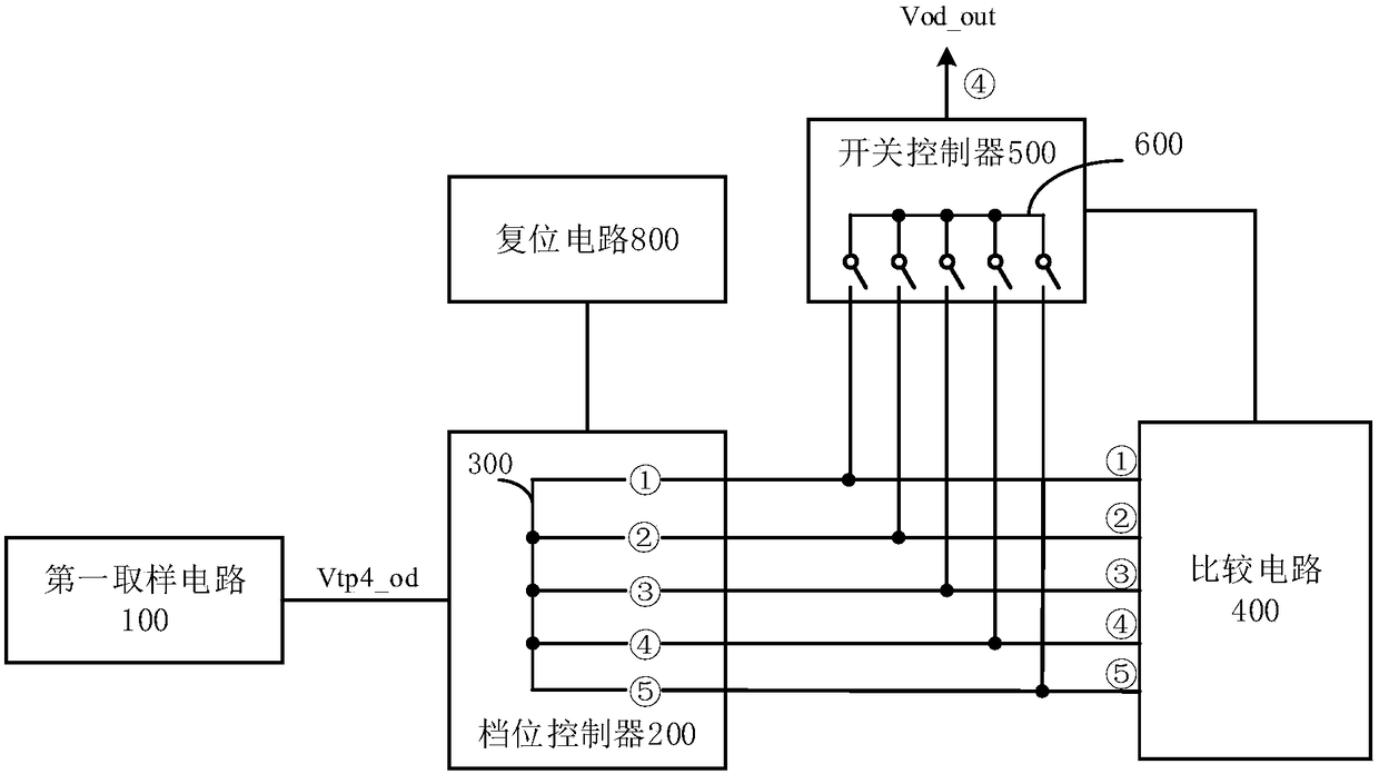
[0056] In order to solve the flickering problem caused by signal attenuation, Embodiment 1 of the present invention provides a video signal adjustment device. The schematic diagram of the device is shown in figure 1 As shown, it includes: a first sampling circuit 100 , a gear controller 200 , at least one gear circuit 300 , a comparison circuit 400 , a switch controller 500 and at least one switch circuit 600 .

[0057] The first sampling circuit 100 is electrically connected to the gear controller 200; the gear controller 200 is electrically connected to at least one gear circuit 300; at least one gear circuit 300 is connected to the comparison circuit 400, and is electrically connected to at least one switch circuit 600 respectively. Connection; the comparison circuit 400 is electrically connected to the switch controller 500 ; the switch controller 500 is electrically connected to at least one switch circuit 600 .

[0058] The working principle of the video signal adjustme...

Embodiment 2

[0096] Corresponding to Embodiment 1, Embodiment 2 of the present invention provides a method for adjusting a video signal. The flow chart of the method is shown in Figure 4 shown, including:

[0097] S1. Acquire a first video signal at a first sampling point.

[0098] The first sampling point is a sampling point at the output end of the driving circuit, which can be represented by TP4; the acquired first video signal Vtp4_od is the video signal output by the driving circuit.

[0099] S2. Perform at least one gear adjustment on the first video signal to generate at least one corresponding gear signal.

[0100] In a preferred embodiment, five gear adjustments are performed on the first video signal, and the five gear circuits 300 involved are respectively the first pre-emphasis gear, pre-emphasis and swing (Swing) gear , the first swing gear, the second pre-emphasis gear and the second swing gear. Depending on user requirements, any one of the five gear circuits 300 may be...


PUM


Abstract

The embodiment of the invention provides a video signal adjustment device, and a video signal adjustment method. The device comprises a first sampling circuit, a gear controller, at least one gear circuit, a comparison circuit, a switch controller, and at least one switch circuit; the first sampling circuit is electrically connected with the gear controller; the gear controller is electrically connected with the at least one gear circuit; the at least one gear circuit are electrically connected with the comparison circuit and are electrically connected with the at least one switch circuit respectively; the comparison circuit is electrically connected with the switch controller; and the switch controller is electrically connected with the at least one switch circuit. By adoption of the method, the attenuation of the video signal during transmission in the prior art can be reduced.

Description

technical field [0001] The present invention relates to the technical field of signal processing, in particular, the present invention relates to a video signal adjustment device and an adjustment method. Background technique [0002] In an existing display device, a video signal is transmitted between a driving circuit and a display screen through a video signal interface, such as an embedded video signal interface EDP (Embedded DisplayPot). The matching between the video signal output by the drive circuit and the video signal received by the display screen is very important to the display effect. When the attenuation exceeds a certain standard, if the video signal output by the drive circuit matches the video signal received by the display screen Poor, there will be undesirable phenomenon of splash screen, affecting product quality. [0003] In actual use, when the video signal of the driving circuit is transmitted to the display screen, the video signal often has differe...

Claims


Application Information

Patent Timeline
Patent Type & Authority Applications(China)
IPC IPC(8): H04N5/14
CPCH04N5/14G09G5/00G09G2330/12G09G5/006G09G2310/0245G09G2320/0247H04N17/045
Inventor 闵泰烨张智唐秀珠陈帅唐滔良田振国梁雪波胡双熊丽军董兴
Owner BOE TECH GRP CO LTD
Features
  • R&D
  • Intellectual Property
  • Life Sciences
  • Materials
  • Tech Scout
  • Unparalleled Data Quality
  • Higher Quality Content
  • 60% Fewer Hallucinations
Learn More