
Ward environment monitoring system

An environmental monitoring and environmental monitoring technology, applied in the field of medical monitoring, can solve the problems of limited transmission range, insufficient scalability, cumbersome wiring, etc., and achieve the effect of overcoming wiring troubles and realizing remote real-time monitoring

Inactive Publication Date: 2018-07-13
陈剑桃
View PDF6 Cites 12 Cited by
  • Summary
  • Abstract
  • Description
  • Claims
  • Application Information

AI Technical Summary

Problems solved by technology

[0004] However, the existing medical monitoring systems basically use manual ward rounds or electrical signal connection lines to connect va

Method used


Image

  • Ward environment monitoring system
  • Ward environment monitoring system
  • Ward environment monitoring system

Examples


Embodiment Construction

[0014] The present invention is further described in conjunction with the following examples.

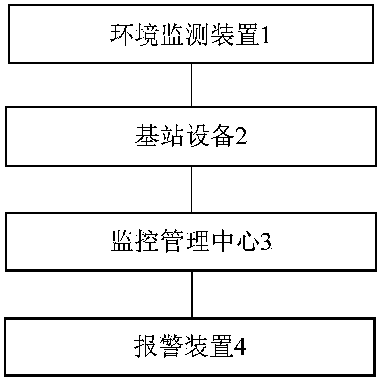
[0015] see figure 1 A ward environment monitoring system provided in this embodiment includes an environment monitoring device 1, a base station device 2, and a monitoring management center 3 that are sequentially connected by communication; Multiple sensor nodes form a wireless sensor network for sensing and collecting ward environment information through self-organization; the ward environment information collected by the sensor nodes is finally transmitted to the base station device 2, and then the base station device 2 will receive The environmental information of the ward is transmitted to the monitoring and management center 3 for centralized processing, storage and display.

[0016] Wherein, the sensor nodes include temperature and humidity integrated sensors, gas sensors and / or light sensors.

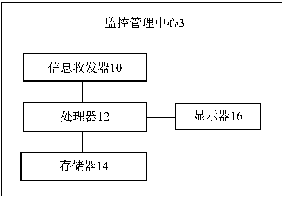
[0017] Optionally, as in figure 2 As shown, the monitoring and management cen...


PUM


Abstract

The invention provides a ward environment monitoring system. The ward environment monitoring system comprises an environment monitoring device, base station equipment and a monitoring management center connected successively in a communicating manner; wherein the environment monitoring device comprises a plurality of sensor nodes randomly deployed in a set ward monitoring area, and the plurality of sensor nodes form a wireless sensor network used for sensing and collecting the ward environment information through a self-organized manner; and the ward environment information collected by sensornodes is finally transmitted to the base station equipment, so that the base station equipment sends the received ward environment information to the monitoring management center for centralized processing, storage and display. The ward environment monitoring system realizes the real-time monitoring of the ward environment by means of the wireless sensor network technology.

Description

technical field [0001] The invention relates to the field of medical monitoring, in particular to a ward environment monitoring system. Background technique [0002] Wireless sensor network is a special wireless self-organizing network, which consists of a large number of sensors to perceive, collect, process and transmit information in the network coverage area, and send it to the network owner. It does not require a high transmission bandwidth, but only requires low transmission delay and low power consumption. There are many nodes in the network and are widely distributed, which can meet the needs of various miniaturized and low-cost equipment (such as temperature adjustment devices, lighting controllers, environmental protection, etc.) Detection sensors, etc.) can be widely used in industry, agriculture, medical treatment and daily life. [0003] In terms of medical care, with the modernization of the economy, the improvement of people's living standards, and the rapid ...

Claims


Application Information

Patent Timeline
IPC IPC(8): H04W4/38H04W40/10H04W40/22H04W84/18H04L12/733G08B25/10H04L45/122
CPCH04L45/122H04W40/10H04W40/22H04W84/18G08B25/10
Inventor 陈剑桃
Owner 陈剑桃
Learn More