Skull-mounted deep brain stimulator

A technology of connectors and electrical connection parts, which can be used in treatment, electrotherapy, etc., and can solve problems such as nerve stimulation treatment damage, inconvenient extension distance, and poor electrical connections.

Active Publication Date: 2018-07-17
BOSTON SCI NEUROMODULATION CORP
View PDF12 Cites 7 Cited by
  • Summary
  • Abstract
  • Description
  • Claims
  • Application Information

AI Technical Summary

Problems solved by technology

As an example, the extended distance between the IPG electronics (under the collarbone) and the treatment site (the brain, near the top of the head) is inconvenient due to the long tunnel required through the patient
Furthermore, if an extender lead 28 is used, the possibility of a poor electrical connection between the electrode terminal 20 on the lead 18 and the receptacle 30 of the extender lead 28 could lead to disruptive neurostimulation therapy

Method used


Image

  • Skull-mounted deep brain stimulator
  • Skull-mounted deep brain stimulator
  • Skull-mounted deep brain stimulator

Examples


Embodiment Construction

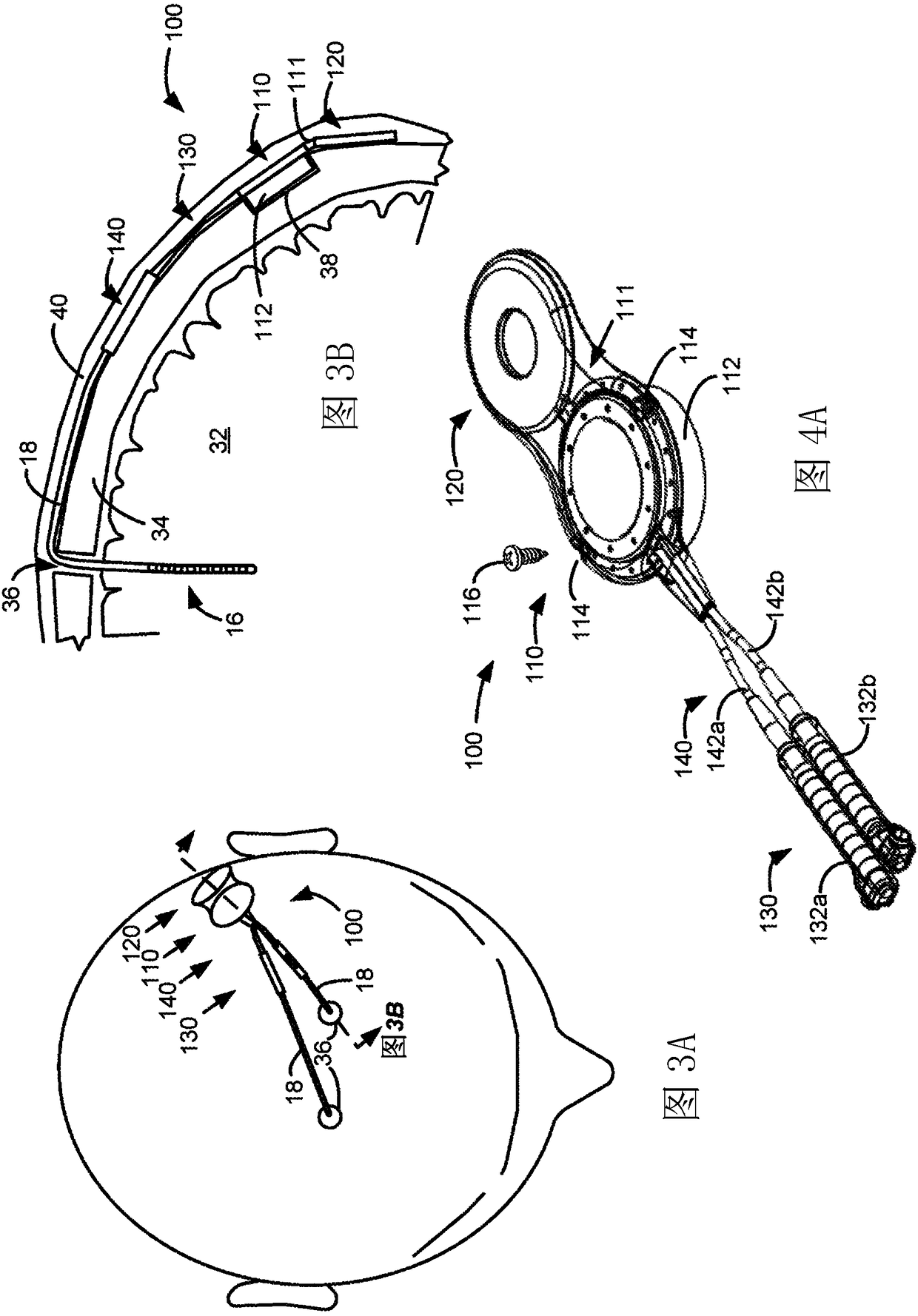
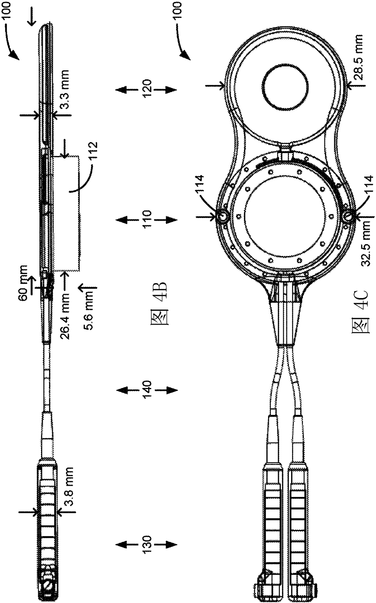
[0019] Figure 3A and 3B A first example of a modified DBS IPG device 100 as implanted in a patient is shown in and in Figures 4A-4C It is shown in isolation and in perspective, side and top-down views, respectively. Such as Figure 3A As shown, looking at the top of a DBS patient's head, the IPG 100 is designed to lie generally flat against the patient's skull, and preferably over the patient's ear near the temporal or parietal bones. This placement is preferred because the skull in these locations is generally flat, thus allowing the IPG 100 to sit relatively flat. However, perfect skull flatness is not required because the IPG 100 is flexible in certain locations, such as Figure 3B shown in the cross-section.

[0020] IPG 100 is generally divided into four sections: electronics section 110 , charging coil section 120 , connector block section 130 , and electrode lead section 140 . Also included in this example are the left and right connector blocks 132a and 132b, s...


PUM


Abstract

The present invention discloses an implantable pulse generator (IPG) operable as a deep brain stimulator (DBS) which is mountable to the skull of a DBS patient, and which therefore is much closer to the site of intended therapy. The IPG includes an electronics section, a charging coil section, a connector block section configured to connect to the proximal end of implanted leads, and an electrodewire section connecting the connector block section to the electronics section. The electronic section includes a housing that is position able into a hole formed in the patient's skull. Once so positioned, the housing may be affixed to the skull via bone screws. The charging coil section may be separate from and non-overlapping with the electronics section, or the charging coil section may encircle the electronics section.

Description

technical field [0001] The present application relates to implantable pulse generators (IPGs), such as deep brain stimulators (DBS). Background technique [0002] Implantable stimulation devices deliver electrical stimulation to nerves and tissues for the treatment of various biological disorders, such as pacemakers for cardiac arrhythmias; defibrillators for heart fibrillation; Cochlear stimulators; Retinal stimulators to treat blindness; Muscle stimulators to produce coordinated limb movements; Spinal cord stimulators to treat chronic pain; Cortical and deep brain stimulators to treat movement and psychological disorders ( DBS); and other neurostimulators for urinary incontinence, sleep apnea, shoulder subluxation, and more. The following description will generally focus on using the present invention within a deep brain stimulation (DBS) system. However, the present invention may find applicability to any implantable pulse generator (IPG) or any IPG system. [0003] Su...

Claims


Application Information

Patent Timeline
Patent Type & Authority Applications(China)
IPC IPC(8): A61N1/375
CPCA61N1/3752A61N1/3754A61N1/37223A61N1/3787
Inventor 威廉·G·奥林斯基
Owner BOSTON SCI NEUROMODULATION CORP
Why Eureka
Try Eureka