
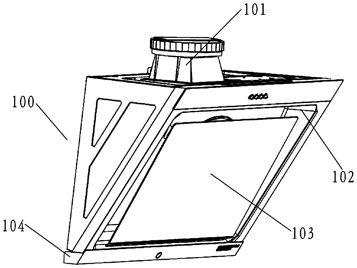
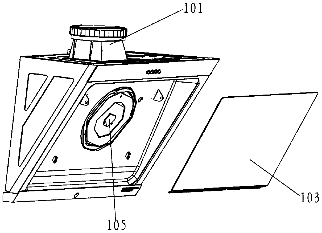
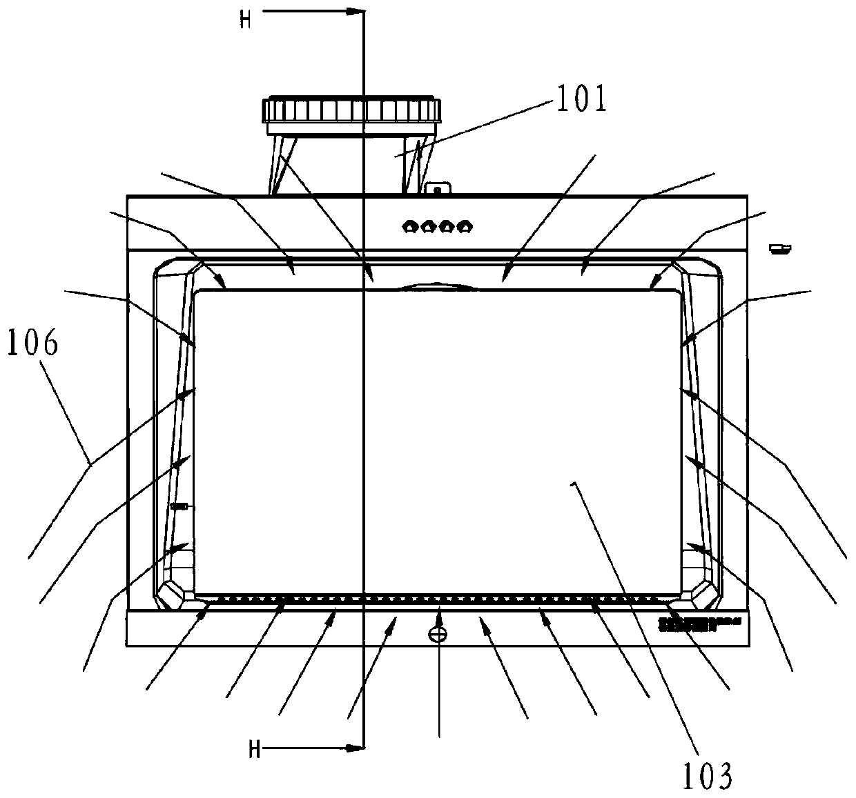
a range hood

A range hood and air intake technology, applied in the field of kitchen appliances, can solve the problems of low air intake efficiency, loss of air volume, poor smoking effect, etc., and achieve the effects of increasing smoke collecting area, large volume and stable structure

Active Publication Date: 2019-07-30
WUHU MIDEA SMART KITCHEN APPLIANCE MFG CO LTD
View PDF5 Cites 0 Cited by
  • Summary
  • Abstract
  • Description
  • Claims
  • Application Information

AI Technical Summary

Problems solved by technology

[0007] The purpose of the present invention is to provide a range hood with simple structure, reasonable design, strong structural strength and stability, and good smoke collection and smoking effects, so as to solve the problem that the deflector of the existing range hood only needs to be stretched. The cavity has the problems of low air intake efficiency, easy to cause loss of air volume and poor smoking effect

Method used


Image

  • a range hood
  • a range hood
  • a range hood

Examples


Embodiment 1

[0052] Such as Figure 5 to Figure 18 As shown, the embodiment of the present invention provides a range hood 200, which includes a box body and an air intake front assembly installed on the box body. The air intake front assembly includes a deflector 221 and at least two air intake nets 241. The left and right sides of the flow plate 221 are respectively provided with a first air inlet cavity 2211 and a second air inlet cavity 2212 protruding toward the direction of the box body. The first air inlet cavity 2211 and the second air inlet cavity 2212 Each is provided with at least one air inlet; the air inlet net 241 is arranged at the air inlet, and the air inlet net 241 is set in one-to-one correspondence with the air inlet.

[0053] The range hood 200 provided by this application adopts double-cavity negative pressure distribution, which has great advantages in collecting smoke and smoking, especially for double-cookers. Specifically, by setting up two air inlet cavities on t...

Embodiment 2

[0087] The difference with the technical solution of Embodiment 1 is:

[0088] Such as Figure 19 to Figure 20 As shown, in this embodiment, the longitudinal section shapes of the first air inlet cavity 2211 and the second air inlet cavity 2212 are both triangular, and one or more of the four cavity surfaces of the first air inlet cavity 2211 One or more of the four cavity surfaces of the first and second air inlet cavity 2212 are provided with air inlets.

[0089] Both the first air inlet cavity 2211 and the second air inlet cavity 2212 on the deflector 221 preferably adopt the structure of a triangular cavity, and the first air inlet cavity 2211 and the second air inlet cavity 2212 are all provided with inlets. tuyere. Wherein, each triangular cavity includes four cavity surfaces, one or more of the four cavity surfaces of the first air inlet cavity 2211 and one of the four cavity surfaces of the second air inlet cavity 2212 Air inlets are provided on one or more of the a...


PUM


Abstract

The invention relates to the technical field of kitchenware, in particular to a range hood. The range hood which comprises a box body and an air inlet front end assembly arranged on the box body; theair inlet front end assembly comprises a guide plate and at least two air inlet meshes; and a first air inlet cavity and a second air inlet cavity which are formed towards the box body direction in araised manner are formed on the left side and the right side of the guide plate. By adopting two-cavity negative pressure distribution, the range hood has great smoke collection and suction advantageswith regard to double cookers, gas flowing in can be uniformly distributed and tends to the two sides of the guide plate advantageously, the smoke collection areas of the left side and the right sideof the range hood are increased, and effective improvement of the oil smoke suction effect is facilitated advantageously; the first air inlet cavity and the second air inlet cavity are each providedwith at least one air inlet, the air inlet meshes are arranged at the air inlets and correspond to the air inlets one to one, and the flowing-in smoke is guided, so that the gas inlet effect is ensured and oil is effectively separated; and the range hood is simple in structure, reasonable in design, good in smoke collection and suction effect and high in practicability.

Description

technical field [0001] The invention relates to the technical field of kitchen utensils, in particular to a range hood. Background technique [0002] At present, what users use in their homes is generally a double stove, with two burners on the left and right. The cooking utensils are located on both sides of the hood, and the general range hood has only one air inlet and the air inlet is placed in the middle. It is generally difficult to suck and exhaust the oil fumes on both sides with the central air inlet. [0003] In view of the above problems, the current technical solutions generally solve the problem by increasing the left and right, front and rear dimensions of the smoke collecting cavity. The increased size of the smoke collection cavity can form a certain size of smoke control area. Generally, the larger the size, the larger the smoke control area. For example, a certain brand of series fan has a bottleneck in the increase of air volume, and the left and right di...

Claims


Application Information

Patent Timeline
Patent Type & Authority Patents(China)
IPC IPC(8): F24C15/20
CPCF24C15/20
Inventor 宋祖龙蒋济武刘凡继何新奎闫亮彭小康
Owner WUHU MIDEA SMART KITCHEN APPLIANCE MFG CO LTD
Learn More