Touch-panel electrode bridging structure

A bridging structure, touch panel technology, applied in the direction of electrical digital data processing, instruments, data processing input/output process, etc., can solve the problems of parts damage, insufficient conduction rate, poor conduction rate, etc., to reduce The effects of manufacturing costs, reducing structural levels, and reducing transmission loss

Inactive Publication Date: 2018-07-20
MIRACLETOUCH TECH
View PDF4 Cites 0 Cited by
  • Summary
  • Abstract
  • Description
  • Claims
  • Application Information

AI Technical Summary

Problems solved by technology

[0004] It can be seen from the above description that the signal line needs to be very accurate when receiving and transmitting the measured voltage value, otherwise it will directly affect the accuracy of its coordinate calculation. However, the existing five-wire resistive touch panel is as follows: Use the silver wire 25 on the lower surface of the conductive film 20 to transmit, and then gather the silver wire 25 at the corresponding soft board signal contact, and lead it out through a conductive bridging body. Due to the long distance of the silver wire 25, there will be attenuation during transmission. The problem is that its conduction rate cannot be improved, which affects its sensitivity and accuracy
[0005] In other words, due to the poor conductivity of the upper and lower conductive layers 11 and 21 of the existing five-wire resistive touch panel, it is necessary to increase the operating force of the touch panel to overcome this defect. However, this Not only is there a phenomenon of power consumption, but also it is easy to cause the touch panel to heat up rapidly during operation, causing damage to parts, thereby shortening its service life. Therefore, how to improve the conduction rate of the upper and lower layers and reduce the operating force of the touch panel is an important aspect of the present invention. Important issues to be improved
[0006] In view of this, the inventor of this case has engaged in research and development and manufacturing experience in related industries for many years, deeply discussed the needs of the aforementioned existing resistive touch panels, and actively sought solutions. After continuous efforts in research and trial production, he finally succeeded. Developed a touch panel electrode bridging structure to overcome the existing inconvenience and trouble caused by the insufficient conduction rate of the upper and lower layers

Method used


Image

  • Touch-panel electrode bridging structure
  • Touch-panel electrode bridging structure
  • Touch-panel electrode bridging structure

Examples


Embodiment Construction

[0031] The present invention is an electrode bridging structure of a touch panel. Among the specific embodiments of the present invention and its components illustrated in the accompanying drawings, all about front and rear, left and right, top and bottom, upper and lower, and horizontal and vertical References are made for convenience of description only, and do not limit the invention, nor limit its components to any position or spatial orientation. The dimensions specified in the drawings and description can be changed according to the design and requirements of the specific embodiment of the invention without departing from the patent scope of the invention.

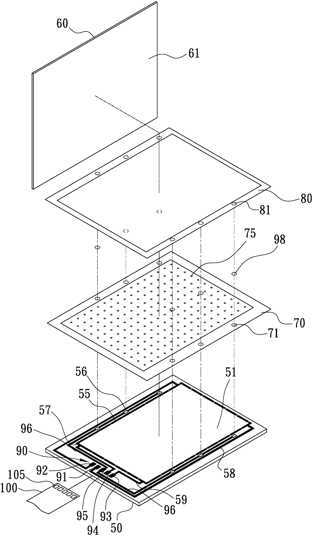
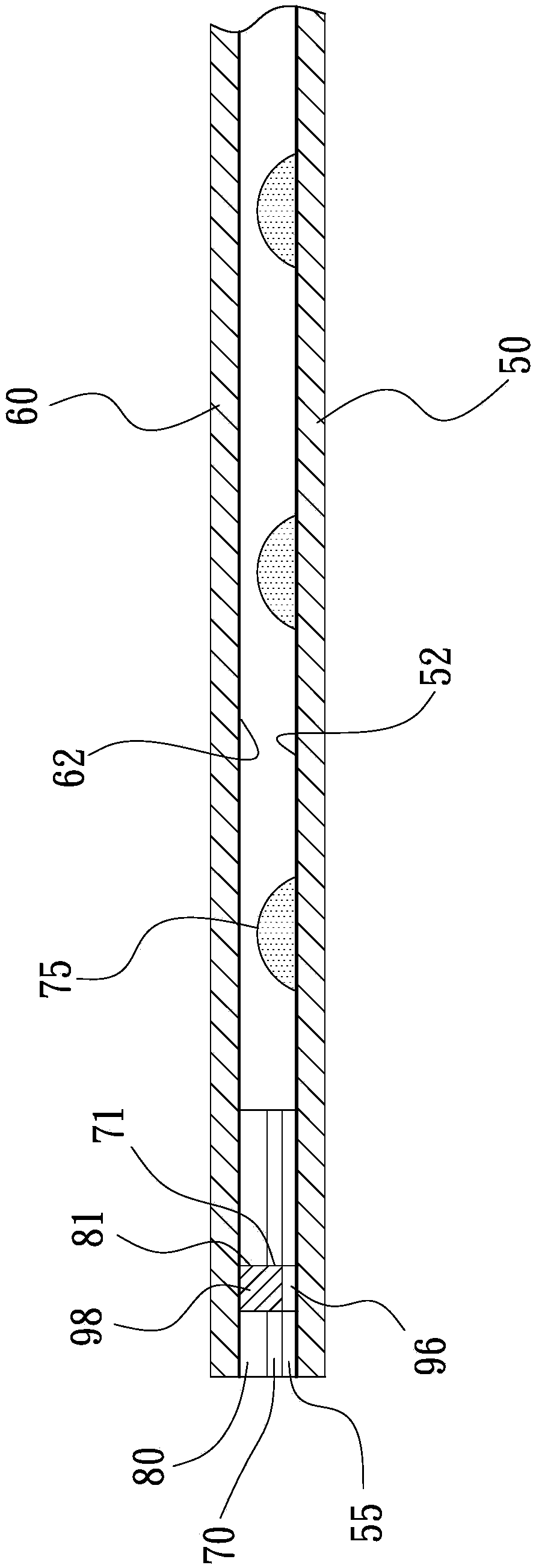
[0032] The present invention is a five-wire resistive touch panel, such as figure 2As shown, the touch panel includes a conductive glass substrate 50 (ITO Glass) and a conductive thin film 60 (ITOFilm) that is attached to the conductive glass substrate 50 in a two-layer structure. The opposite surface of the conduct...


PUM


Abstract

The invention discloses a touch-panel electrode bridging structure, and particularly relates to a touch-panel electrode bridging structure capable of increasing a conduction rate of upper-and-lower-layer electrodes. A touch panel contains a conductive glass substrate and a conductive film disposed on the conductive glass substrate. A ring-shaped electrode circuit is printed around an upper surfaceof the conductive glass substrate to control four wires of an X axis and a Y axis. The structure is characterized in that at least two conductive bridging parts are disposed on at least two opposingsides of the electrode circuit, and all the conductive bridging parts can simultaneously be in conduction with the conductive glass substrate and the conductive film, and are in parallel connection with signal wires. Therefore, the upper and lower electrodes of the touch panel of the invention can utilize the multiple conductive bridging parts in connection with the signal wires to sense conduction, the conduction rate of upper and lower layers is effectively increased, workloads of the touch panel are reduced, and thus the purpose of energy saving is achieved; and compared with the prior art,the structure can reduce a structure hierarchy thereof, and can thus reduce working procedure, shorten working time, and then reduce manufacturing costs of the touch panel.

Description

technical field [0001] The present invention relates to the technical field of touch panels, in particular to a touch panel electrode bridging structure with high conductivity between upper and lower layers, so as to improve the sensitivity and accuracy of touch control. Background technique [0002] Existing resistive touch panels can be divided into four-wire, five-wire, six-wire or eight-wire resistive types, among which the five-wire resistive touch panel is the most common. The general composition of resistive touch panels is as follows figure 1 As shown, it consists of a two-layer structure, including a conductive glass substrate 10 (ITO Glass) and a conductive thin film 20 (ITOFilm) attached to the conductive glass substrate 10, wherein the upper surface of the conductive glass substrate 10 is coated with The conductive layer 11 is printed with a ring-shaped electrode circuit 15 around it, and the conductive glass substrate 10 is printed with a ring-shaped insulating ...

Claims


Application Information

Patent Timeline
Patent Type & Authority Applications(China)
IPC IPC(8): G06F3/045
CPCG06F3/045G06F2203/04103
Inventor 林毓敏林建豪
Owner MIRACLETOUCH TECH
Why Eureka
Try Eureka