Fixing apparatus used for cable head replacement in box body

A technology of fixing device and cable head, applied in the direction of connecting/terminating cable equipment, etc., can solve the problems of explosion of cable terminal head in the cabinet, inconvenient use of the site, limited space, etc., to achieve good safety and convenience, saving time, good practicality

Pending Publication Date: 2018-07-20
GUANGDONG POWER GRID CO LTD +1
View PDF6 Cites 3 Cited by
  • Summary
  • Abstract
  • Description
  • Claims
  • Application Information

AI Technical Summary

Problems solved by technology

With the continuous development of distribution network lines, the load continues to increase, causing the cable terminal in the cabinet to explode or catch fire
Since the cable head is generally in the box, the space in the box is limited, and the reserved length of the cable on the rack is limited at the lower end of the box, so it cannot be pulled out of the reserved cable body to replace the cable head.
The construction environment for replacing the cable head is relatively complicated, and the site is inconvenient to use. It is impossible to use conventional ropes to fix the cable head, and many boxes do not have the conditions for binding or hanging
[0003] At present, the fixing methods for cable head replacement include binding, using wooden sticks, and hanging from the top of the box to bind and fix. These methods have a great impact on the quality of the cable head manufacturing process, and there are many hidden risk points. Moreover, these methods cannot meet people's ever-increasing demand for power and the higher repair time limit for construction units.
In addition, these methods are time-consuming, and there is a danger of falling off in the binding technology, and the shaking of the cable head during production has an impact on the construction process

Method used


Image

  • Fixing apparatus used for cable head replacement in box body

Examples


Embodiment 1

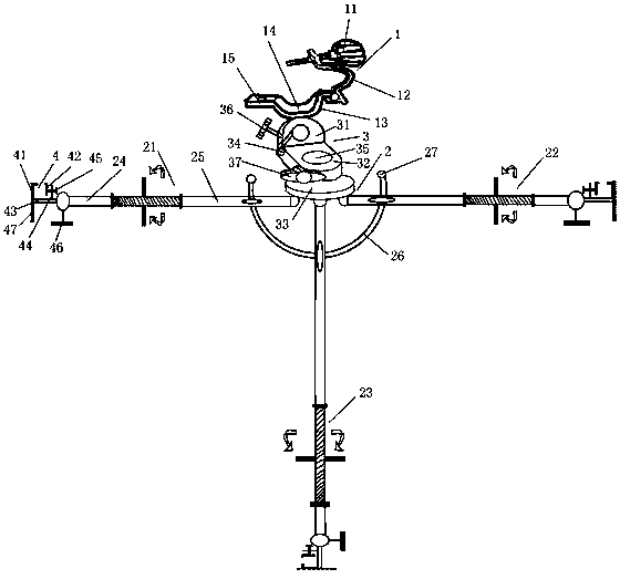
[0024] like figure 1 Shown is the fixing device for replacing the cable head in the box of the present invention, including a cable head holder 11 and a fixing frame 22, and a rotating table is connected between the cable head fixing device 1 and the fixing frame 2; The first telescopic rod 21 supported on both sides, the second telescopic rod 22 and the third telescopic rod 23 supported on the ground or the upper and lower sides of the box, one end of the first telescopic rod 21, the second telescopic rod 22, and the third telescopic rod 23 Both are fixed with the rotary table, and the other end is connected with the clamping assembly 4 fixed with the box; the first telescopic rod 21 and the second telescopic rod 22 are arranged on the same straight line, and the third telescopic rod 23 is connected with the first telescopic rod 21 and the second telescopic rod 23. The straight line where two telescopic rods 22 are located is vertical. When this embodiment is implemented, th...


PUM


Abstract

The invention relates to the technical field of power distribution network auxiliary equipment, more specifically a fixing apparatus used for cable head replacement in a box body. The fixing apparatuscomprises a cable head fixer and a fixed frame; a rotary platform is connected between the cable head fixer and the fixed frame; the fixed frame comprises a first telescopic rod and a second telescopic rod which support the left and right sides of the box body, and a third telescopic rod which supports the ground or the upper and lower sides of the box body; one ends of the first telescopic rod,the second telescopic rod and the third telescopic rod are all fixed with the rotary platform while the other ends are connected with a clamping assembly fixed with the box body; the first telescopicrod and the second telescopic rod are arranged on the same straight line; and the third telescopic rod is perpendicular to the straight line where the first and second telescopic rods are located. Byvirtue of the fixing apparatus, the cable head can be fixed in the box body safely and stably, thereby providing a reliable fixation condition for cable head replacement, saving time in the fixing process, adjusting the cable head in various angles, and achieving relatively high safety and convenience.

Description

technical field [0001] The invention relates to the technical field of distribution network auxiliary equipment, and more specifically, to a fixing device for replacing cable heads in a box. Background technique [0002] With the development of the distribution network cable process, many cities or towns use underground cable laying to replace the operation of overhead lines. With the continuous laying and use of cables, there are extremely complicated cable heads in the matching box-type transformers, distribution boxes, and cable branch boxes. With the continuous development of distribution network lines, the load continues to increase, causing the cable terminal in the cabinet to explode or catch fire. Because the cable head is generally all in the box, the space in the box is limited, and the reserved length of the cable on the shelf is limited at the lower end of the box, so it is impossible to pull it out of the reserved cable body to replace the cable head. The cons...

Claims


Application Information

Patent Timeline
Patent Type & Authority Applications(China)
IPC IPC(8): H02G1/14
CPCH02G1/14
Inventor 欧阳康
Owner GUANGDONG POWER GRID CO LTD
Why Eureka
Try Eureka