Adaptive output current ripple removing circuit and method

An output current, self-adaptive technology, applied in the direction of output power conversion devices, electrical components, etc., can solve the problems of low efficiency of anti-ripple scheme, small current application range, and anti-ripple applications that do not support linear output, etc. The effect of preventing overvoltage protection

Active Publication Date: 2018-07-20
CRM ICBG (WUXI) CO LTD
View PDF14 Cites 14 Cited by
  • Summary
  • Abstract
  • Description
  • Claims
  • Application Information

AI Technical Summary

Problems solved by technology

[0007] In view of the shortcomings of the prior art described above, the purpose of the present invention is to provide an adaptive output current ripple removal circuit and a ripple removal method thereof, which are used to solve the low efficiency of the ripple removal scheme in the prior art and the current application range. Small, does not support thyristor dimming applications, does not support linear output ripple applications, etc.

Method used

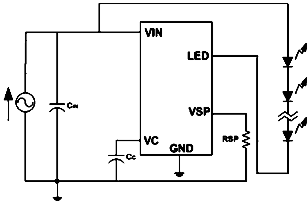
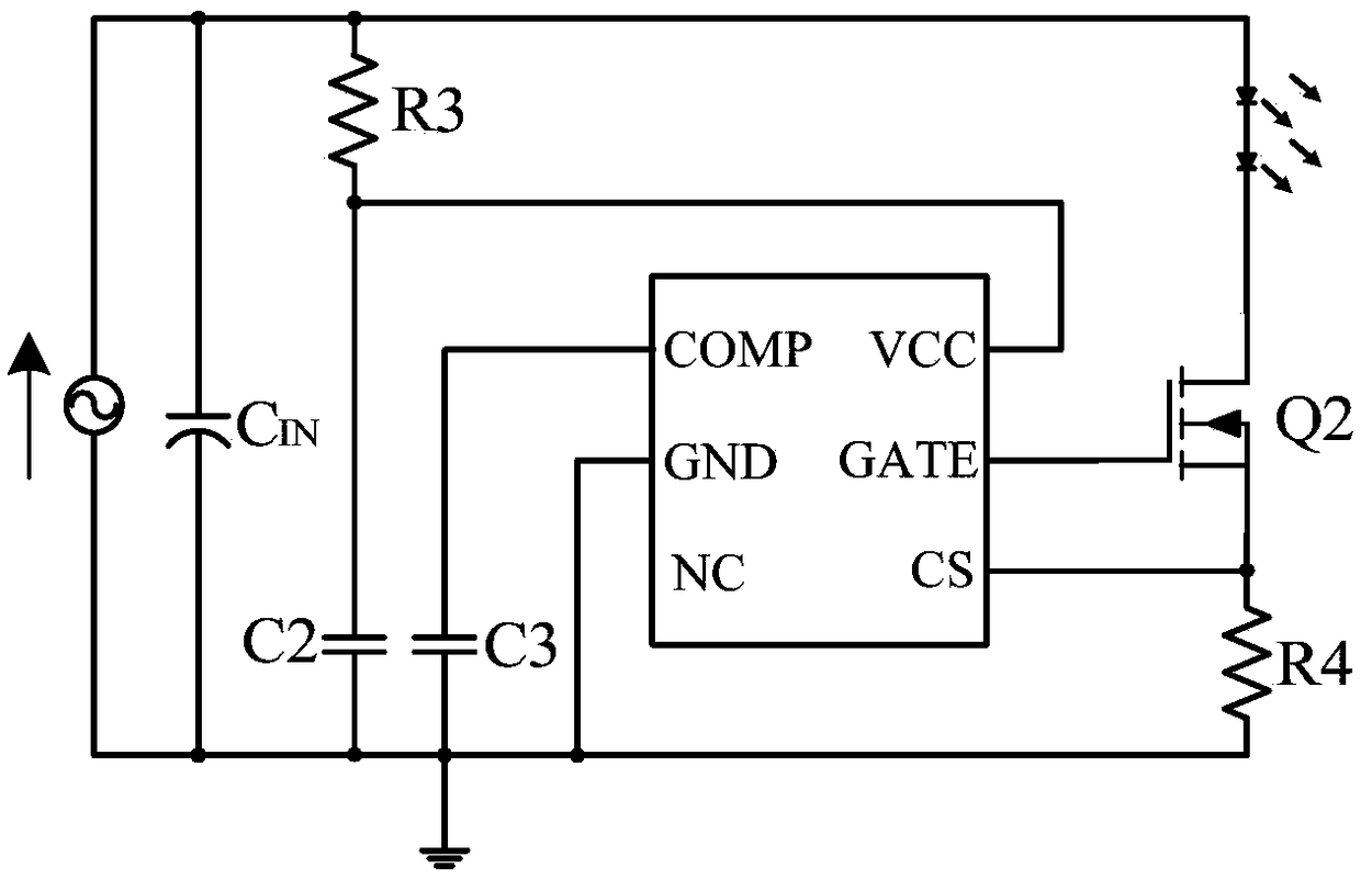

Image

  • Adaptive output current ripple removing circuit and method
  • Adaptive output current ripple removing circuit and method
  • Adaptive output current ripple removing circuit and method

Examples


Embodiment Construction

[0052] Embodiments of the present invention are described below through specific examples, and those skilled in the art can easily understand other advantages and effects of the present invention from the content disclosed in this specification. The present invention can also be implemented or applied through other different specific implementation modes, and various modifications or changes can be made to the details in this specification based on different viewpoints and applications without departing from the spirit of the present invention.

[0053] see Figure 4 ~ Figure 5 . It should be noted that the diagrams provided in this embodiment are only schematically illustrating the basic idea of ​​the present invention, and only the components related to the present invention are shown in the diagrams rather than the number, shape and shape of the components in actual implementation. Dimensional drawing, the type, quantity and proportion of each component can be changed arbi...


PUM


Abstract

The invention provides an adaptive output current ripple removing circuit and method. The method comprises that a negative end voltage of an LED load is detected; when the negative end voltage is lower than a set voltage, a first constant current source is switched off, a second constant current source is switched on and discharges a compensation capacitor, the compensation voltage is reduced, theoutput current is reduced, and the negative end voltage of the LED load is increased; and when the negative end voltage of the LED load is greater than the set voltage, the first constant current source is switched on, the second constant current source is switched off, the first constant current source charges the compensation capacitor, the compensation voltage is increased, the output currentis increased, and the negative end voltage of the LED load is reduced. Only the minimal value of the output ripple voltage is detected, and the method and device are suitable for ripple removing application of silicon controlled rectifier light modulation and linear output; and overheating protection does not influence work of a pre-stage system, flickering is avoided from influencing the experience, and heat loss of an MOSFET can be controlled independently.

Description

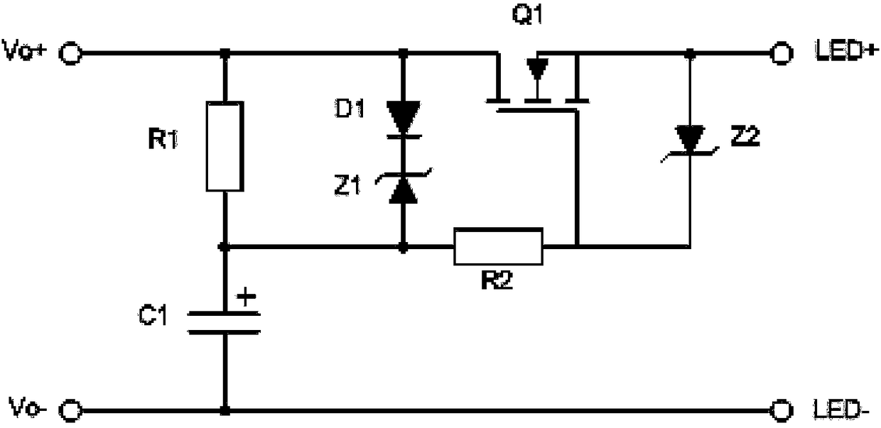
technical field [0001] The invention relates to the field of circuit design, in particular to an adaptive output current elimination ripple circuit and a ripple elimination method thereof. Background technique [0002] Usually in the application of high power factor (PF, Power Factor), due to the limitation of the output capacitor, the output current has the AC component of the power frequency, which may cause flicker in some occasions, and it is necessary to add a ripple circuit to filter the power frequency Element. [0003] Such as figure 1 Shown is a traditional MOSFET ripple removal circuit, including resistor R1 and capacitor C1 connected in series and parallel to the output terminal, the positive-phase output terminal Vo+ is connected to the positive terminal LED+ of the LED through the transistor Q1, and the inverting output terminal Vo- is connected to the negative terminal of the LED LED-; the positive pole of diode D1 is connected to the positive phase output te...

Claims


Application Information

Patent Timeline
Patent Type & Authority Applications(China)
IPC IPC(8): H02M1/14H02M1/32
CPCH02M1/143H02M1/32H02M1/327
Inventor 刘军吴泉清王兆坤
Owner CRM ICBG (WUXI) CO LTD
Why Eureka
Try Eureka