
Cab roof deflector device

A technology for a shroud and a cab, which is applied in the field of the cab top shroud device, can solve the problems that the height adjustment amount of the top shroud 1A cannot be continuous and is difficult to adjust, and achieves convenient, quick and easy height adjustment. effect of adjustment

Active Publication Date: 2019-09-24
ANHUI JIANGHUAI AUTOMOBILE GRP CORP LTD
View PDF8 Cites 0 Cited by
  • Summary
  • Abstract
  • Description
  • Claims
  • Application Information

AI Technical Summary

Problems solved by technology

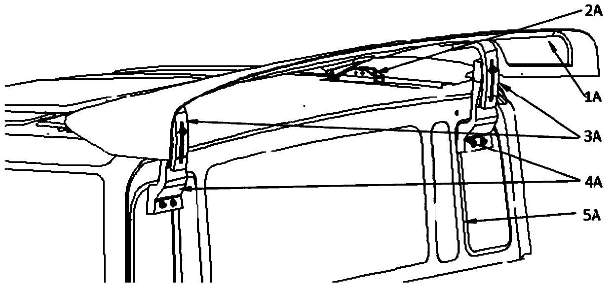
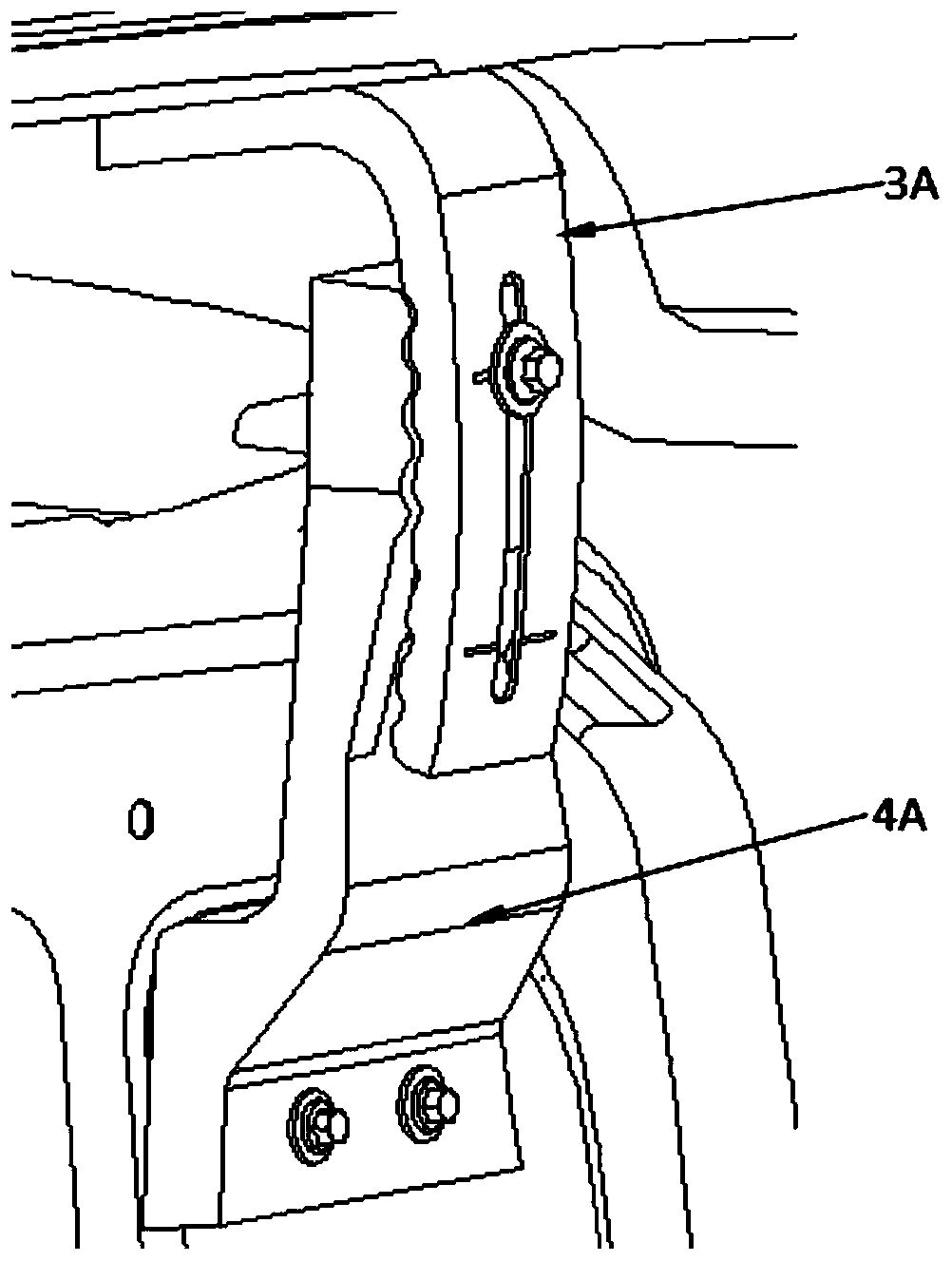
[0007] (3) The upper bracket 3A and the lower bracket 4A realize the adjustment limit through the engagement of the concave-convex structure, which makes the height of the top shroud 1A be fixed only when the upper bracket 3A and the lower bracket 4A are engaged, resulting in the top diversion The height adjustment of the cover 1A cannot be continuous, so it is difficult to adjust to the ideal height required by the user

Method used


Image

  • Cab roof deflector device
  • Cab roof deflector device
  • Cab roof deflector device

Examples


Embodiment Construction

[0036] In order to enable those skilled in the art to better understand the technical solution of the present invention, the solution will be further described in detail below in conjunction with specific embodiments.

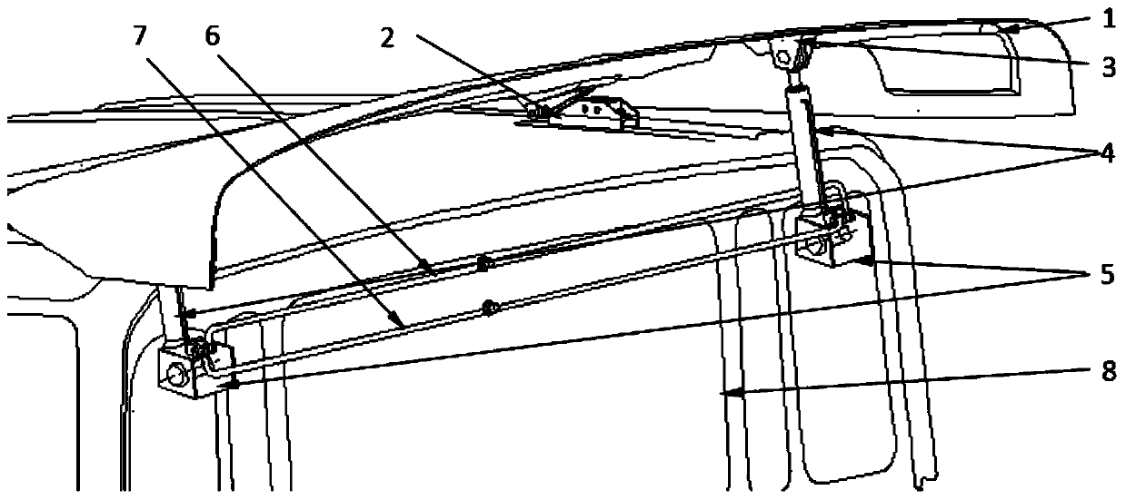
[0037] Such as image 3 As shown, the embodiment of the present invention provides a cab top wind deflector device, which includes a top wind deflector 1, a top cover 8 and a hinge 2, and the hinge 2 is used to connect the front portion of the top wind deflector 1 and the top cover 8, it also includes a fixed frame 3, a mounting frame 5, a power expansion part 4 and a control device, the fixed frame 3 is arranged at the rear of the top shroud 1, the mounting frame 5 is arranged at the rear of the top cover 8, and the installation The frame 5 is opposite to the fixed frame 3; the power telescopic part 4 is fixed on the mounting frame 5, and the push rod of the power telescopic part 4 is connected with the fixed frame 3; the control device is used to drive the po...


PUM


Abstract

The invention provides a cab roof fairing device which comprises a roof fairing, a top cover and hinges. The hinges are used for connecting the front portion of the roof fairing with the upper portionof the top cover. The cab roof fairing device further comprises a fixing frame, installation frames, power telescopic pieces and a control device, the fixing frame is arranged on the rear portion ofthe roof fairing, and the installation frames are arranged on the rear portion of the top cover and are opposite to the fixing frame; the power telescopic pieces are fixed to the installation frames,and push rods of the power telescopic pieces are connected with the fixing frame; and the control device is used for driving the power telescopic pieces, so that the push rods stretch out and retractback. By the adoption of the cab roof fairing device, the power telescopic pieces are driven through the control device, so that the push rods of the power telescopic pieces stretch out and retract back, the height of the roof fairing is adjusted, and labor is saved; meanwhile, the height of the roof fairing is adjusted conveniently and quickly; and the push rods stretch out, so that the height adjusting amount of the roof fairing is continuous, and the roof fairing can be easily adjusted to the ideal height required by a user.

Description

technical field [0001] The invention relates to the technical field of vehicle component structures, in particular to a cab top wind deflector device. Background technique [0002] The height of the top shroud in the top shroud device of the cab on the existing heavy truck is usually adjustable to meet the user's requirements for reducing wind resistance when transporting goods of different heights. [0003] Existing cab roof spoiler installations such as figure 1 As shown, it includes a top wind deflector 1A, two hinges 2A, two upper brackets 3A and two lower brackets 4A respectively corresponding to the two upper brackets. Two of the hinges 2A are respectively fixed on the left and right sides of the upper part of the top cover 5A to realize the connection between the front part of the top air guide 1A and the top cover 5A; the two upper brackets 3A are installed on the top air guide by bolts respectively. The left and right sides of the rear part of the cover 1A; the tw...

Claims


Application Information

Patent Timeline
Patent Type & Authority Patents(China)
IPC IPC(8): B62D35/00F15B11/17F15B13/06
Inventor 徐金志曹文超单长洲张海英胡垚蒯旭辉
Owner ANHUI JIANGHUAI AUTOMOBILE GRP CORP LTD
Learn More