
Inverse kinematics solution method for spatial function track movement of multi-joint mechanical arm

A multi-joint manipulator, trajectory motion technology, applied in manipulators, program-controlled manipulators, control/regulation systems, etc.

Active Publication Date: 2018-07-27
ZHEJIANG UNIV
View PDF5 Cites 3 Cited by
  • Summary
  • Abstract
  • Description
  • Claims
  • Application Information

AI Technical Summary

Problems solved by technology

However, there is no special inverse kinematics solution method for the motion of this input trajectory function, and the present invention proposes a method for inverse kinematics solution for this kind of motion situation

Method used


Image

  • Inverse kinematics solution method for spatial function track movement of multi-joint mechanical arm
  • Inverse kinematics solution method for spatial function track movement of multi-joint mechanical arm
  • Inverse kinematics solution method for spatial function track movement of multi-joint mechanical arm

Examples


Embodiment Construction

[0015] The solution process of the present invention will be described in more detail below with reference to the accompanying drawings.

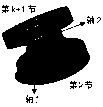
[0016] Assuming that the total number of joints of the multi-joint manipulator is n, the sequence from the motor to the outside is the nth section, the n-1th section...the 1st section, the length of each joint is L, and the movement time is t. The present invention explores the motion of each joint in the case of three-dimensional motion from two motion modes. Indicate as figure 1 .

[0017] (1) Operation space and joint space

[0018] Since the space curve equation has many expressions, the following equations are selected to describe the space trajectory for the convenience of description:

[0019]

[0020] Among them, x, y, and z respectively represent the three-dimensional coordinates of the space curve trajectory. In the above expression, given the function expression of x and z to the independent variable y, it is easy to get a...


PUM


Abstract

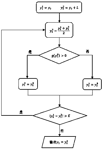
The invention provides an inverse kinematics solution method for spatial function track movement of a multi-joint mechanical arm. The mapping relations between operating space and joint space, and thejoint space and driving space during the movement of the multi-joint mechanical arm according to an established trajectory function are solved. After the spatial trajectory function is established, the inverse kinematics solution method for the spatial function track movement of the multi-joint mechanical arm is capable of outputting postures of all joints at all time (specifically, the end positions of all the joints) and the rope length of each driving rope. When solving the mapping relation between the operating space and the joint space, the relation is numerically solved by a dichotomy in numerical methods. When solving the mapping relation between the joint space and the driving space, a transformation matrix of each joint coordinate system relative to a base coordinate system can be obtained by an algorithm, so that the rope length of each driving rope is obtained.

Description

technical field [0001] The invention provides an inverse kinematics solution method for the space function trajectory motion of a multi-joint manipulator. Background technique [0002] The current robotic arms are generally rigid structures with 5-7 degrees of freedom, and the flexibility of the arm body is poor, which cannot meet the operating requirements in narrow and complex environments. However, the multi-joint manipulator to which the present invention is applicable has many degrees of freedom and flexible and changeable postures, and can meet the operation requirements of the above-mentioned working conditions. [0003] The application of the present invention is mainly in some complex environments with many obstacles, it is necessary to make the mechanical arm move around the obstacles to the designated position according to the given trajectory under the cooperation of the base, and then complete the operation in the designated space. Required work (such as cuttin...

Claims


Application Information

Patent Timeline
IPC IPC(8): B25J9/16
CPCB25J9/1605G05B2219/40317
Inventor 陈正葛子赟李剑鹏宋伟王滔
Owner ZHEJIANG UNIV
Learn More