Small electronic equipment mounting structure based on novel screw

An electronic equipment and installation structure technology, applied in the field of installation structure of small electronic equipment, can solve the problems of cumbersome installation process, increased production cost, troublesome installation process, etc. stable effect

Pending Publication Date: 2018-07-27
HANGZHOU COMMNET
View PDF0 Cites 0 Cited by
  • Summary
  • Abstract
  • Description
  • Claims
  • Application Information

AI Technical Summary

Problems solved by technology

[0004] Although the above-mentioned opening installation method requires fewer parts, the installation process is more troublesome. Not only does it need to be fixed by removing the upper cover of the product, but also the internal components of the product are directly exposed, which is easy to be damaged during installation, resulting in incomplete product functions.
In order to improve the problem of exposed components, some products are further equipped with a protective cover inside the shell. Although this method avoids the probability of product damage during the installation process, it makes the installation process more cumbersome and relatively increases the production cost.
At the same time, this installation method also has a disadvantage, that is, it is easy to be removed, even if there is an alarm device inside the product, it is not easy to identify during the installation process

Method used


Image

  • Small electronic equipment mounting structure based on novel screw
  • Small electronic equipment mounting structure based on novel screw
  • Small electronic equipment mounting structure based on novel screw

Examples


Embodiment 1

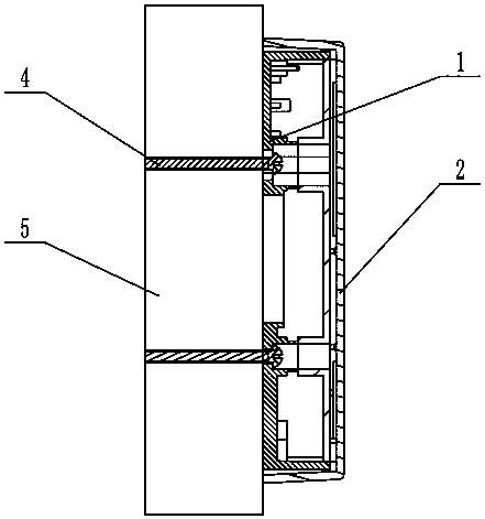
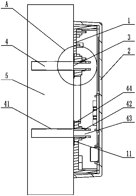
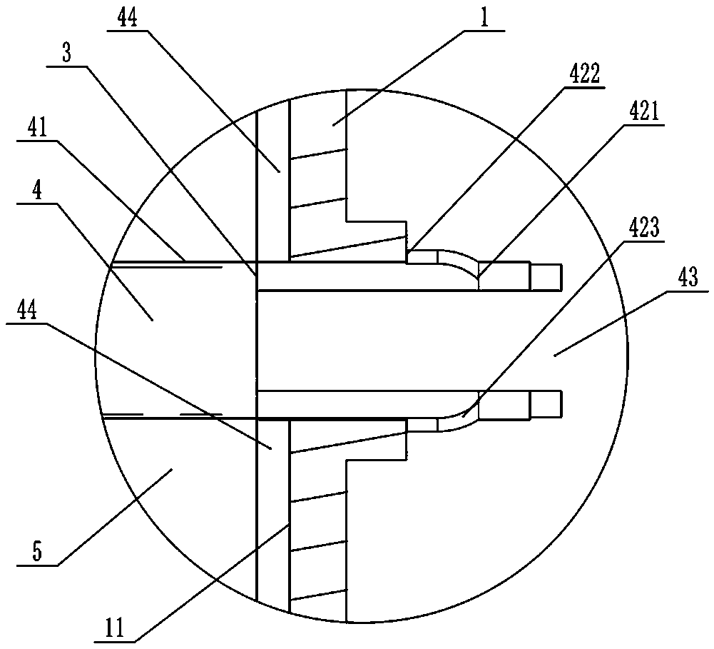
[0021] Such as figure 2 , 3 As shown, the novel screw-based small electronic device installation structure described in this embodiment includes a bottom case 1 for setting electronic devices, and an upper cover 2 that closes the entire case. The bottom of the bottom case 1 is provided with a mounting channel The hole 3 is provided with a buckle screw 4 in the installation through hole 3. The buckle screw 4 includes a fixing section 41 inserted into the fixture 5 and a connecting section matched with the bottom case 1. The connecting section A slit 43 is provided on the axial end, and on the outside of the slit 43, a buckle 42 that gradually increases from the connecting section to the fixed section 41 is provided. The outer diameter of the small end 421 of the buckle is smaller than the installation through hole on the bottom shell 1 3, and the outer diameter of the buckle big end 422 is greater than the inner diameter of the installation through hole 3 on the bottom case 1...


PUM


Abstract

The invention designs a small electronic equipment mounting structure based on a novel screw. The small electronic equipment installation structure comprises a bottom shell for setting up an electronic device and an upper cover for sealing the entire shell; mounting through holes are formed in the bottom of the bottom shell, a buckling screw comprises a fixed section inserted into a fixed object and a connecting section matched with the bottom shell and is arranged in each of the mounting through holes, a notch is formed in the axial end part of the connecting section, and a buckle gradually increasing in the direction from the connecting section to the fixed section is arranged on the outer side of the notch, the external diameter of the small end of the buckle is less than or equal to the internal diameter of each of the mounting through holes in the bottom shell, the external diameter of the large end of the buckle is more than or equal to the internal diameter of each of the mounting through holes in the bottom shell, so that the buckling part of the buckling screw is clamped into the inside of the bottom shell through the corresponding mounting through hole. The structure hasthe characteristic that through direct matching with the bottom shell through the buckling screws, the bottom on the outer side of the bottom shell is directly matched and fixed with the buckling screws.

Description

technical field [0001] The invention relates to a mechanical mounting structure, in particular to a mounting structure suitable for small electronic equipment. Background technique [0002] With the continuous development of radio frequency, sensing, wireless transmission and other technologies, various small electronic devices emerge in endlessly. On the premise of satisfying the socialized and orderly management of these devices, how to realize their simple and quick installation and have the tamper alarm function has always been one of the problems faced by construction units and product designers. At present, most products need to open the protective cover to be fixed on the wall or similar fixtures during installation, which not only brings inconvenience to the construction unit, but also may damage the internal electronic components due to careless operation. Although some products have a protective cover on the circuit part, it makes the installation steps more compl...

Claims


Application Information

Patent Timeline
Patent Type & Authority Applications(China)
IPC IPC(8): H05K5/00
CPCH05K5/0008
Inventor 黎红飞裘晓光严伟苗陈云翔周鸣何晓林
Owner HANGZHOU COMMNET
Why Eureka
Try Eureka