Eureka AIR delivers breakthrough ideas for toughest innovation challenges, trusted by R&D personnel around the world.

Fatigue deformation acceleration test method for cutter bar

A fatigue deformation and accelerated test technology, applied in special data processing applications, instruments, electrical and digital data processing, etc., can solve the problems of long test cycle, low frequency of ordinary fatigue testing machines, etc., to simplify the loading method, speed up The effect of toolholder deformation failure

Active Publication Date: 2018-08-03
YANSHAN UNIV
View PDF3 Cites 1 Cited by
  • Summary
  • Abstract
  • Description
  • Claims
  • Application Information

AI Technical Summary

Problems solved by technology

[0003] The purpose of the present invention is to overcome the problems such as the long fatigue test cycle of the cutter bar and the low frequency of the ordinary fatigue testing machine which cannot meet the accelerated test, and provide a method for the accelerated test of the fatigue deformation of the cutter bar, which has strong operability and low cost. The optimized fatigue deformation accelerated test platform can effectively obtain the deformation life curve of the tool holder and predict the failure time of the tool holder

Method used


Image

  • Fatigue deformation acceleration test method for cutter bar
  • Fatigue deformation acceleration test method for cutter bar
  • Fatigue deformation acceleration test method for cutter bar

Examples


Embodiment

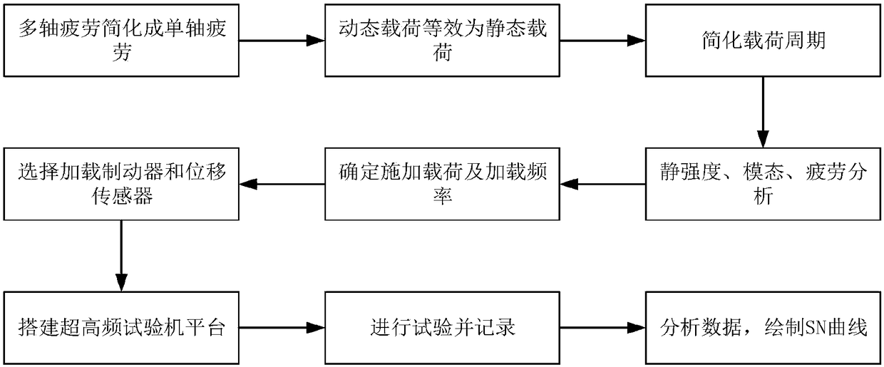
[0028] Taking a cylindrical tool bar with a working speed of 2000r / min, a cutting force of 600-1000N, and a material of 40CrNiMo as an example, the specific implementation steps of this method are introduced.

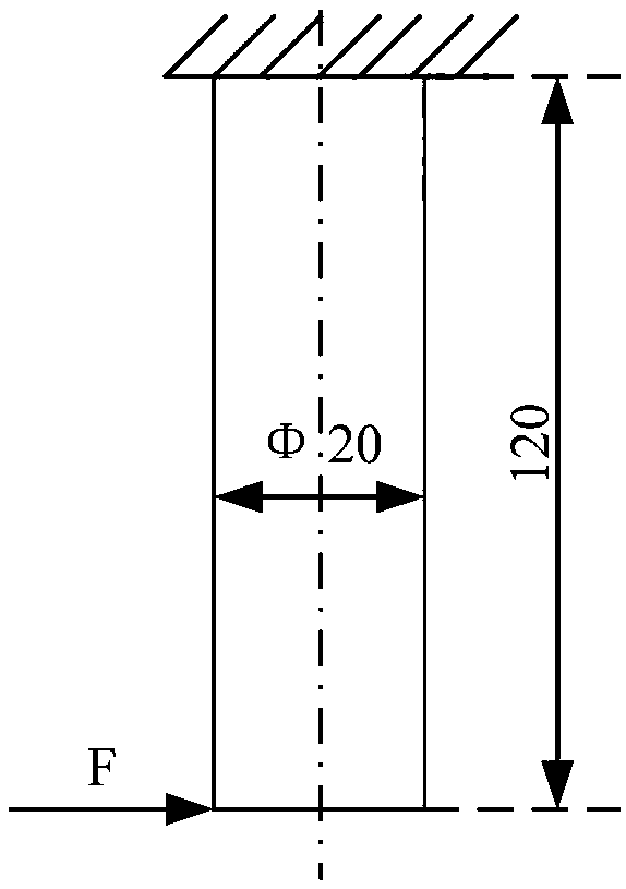
[0029] (1) According to the number of teeth on the cutter rod, the number of fatigue deformation axes of the cutter rod during the cutting process is determined, and the equivalent test method of uniaxial sequential vibration is used to simplify the multi-axial test into a single-axial test problem. At this time, the tool holder can be simplified as a cantilever cylindrical polished rod with a fixed top and a dynamic cutting force at the bottom, such as figure 2 shown; its basic parameters are 120mm in length and 20mm in diameter;

[0030] (2) The dynamic load borne by the tool holder during the actual cutting process is simplified to static load. It is known that the cutting force of the tool holder is in the range of 600-1000N during the cutting process, and 1000N i...


PUM


Abstract

The invention discloses a fatigue deformation acceleration test method for a cutter bar. The content of the method comprises the steps of determining the number of fatigue deformation axes of the cutter bar in a cutting process according to the number of cutter teeth, and enabling a dynamic load borne by the cutter bar in the actual cutting process to be equivalent to a static load by use of a single-axial sequential vibration equivalent test method; calculating an actual loaded frequency of the cutter bar; establishing a cutter bar model in a CAD (Computer-Aided Design), importing the cutterbar model into finite element software ANSYS, analyzing a maximum load which can be exerted in the case of guaranteeing that a failure mechanism of the cutter bar is not changed, analyzing a modalityof the cutter bar, and determining the load magnitude and the frequency magnitude which are exerted at an acceleration test; selecting a loading device and a detection device; establishing a super-high frequency testing machine platform for testing, enabling the detected detection device to perform in-situ detection of a deformation situation of the cutter bar, record and analyze detection data; and establishing a fatigue deformation acceleration model and drawing a fatigue deformation SN curve of the cutter bar.

Description

technical field [0001] The invention belongs to the field of tool fatigue life research and relates to an accelerated test method for tool bar fatigue deformation. Background technique [0002] As an essential element of metal cutting, cutting tools are widely used in the field of modern machinery manufacturing. As the direct executor of the cutting process of the machine tool, the tool often works continuously for several hours under harsh working conditions such as high frequency, high speed, high temperature, and impact, which leads to fatigue deformation and failure of the tool bar during the cutting process, and cannot meet the cutting accuracy. In view of this problem, the fatigue test of the cutter bar is carried out to obtain the deformation life curve of the tool bar, which can accurately predict the normal working time of the tool bar, and effectively reduce the economic loss caused by the fatigue deformation failure of the tool bar caused by the machining error of...

Claims


Application Information

Patent Timeline
Patent Type & Authority Applications(China)
IPC IPC(8): G06F17/50
CPCG06F30/17G06F30/23G06F2119/06
Inventor 吴凤和裴国斌王朝华孙银旭
Owner YANSHAN UNIV
Why Eureka
Eureka Blog
Learn More