Eureka AIR delivers breakthrough ideas for toughest innovation challenges, trusted by R&D personnel around the world.

Rotary connector

A technology of rotating connectors and rotating bodies, applied in the direction of flexible/rotatable wire connectors, vehicle connectors, connections, etc., can solve the problems of complex wiring structure, difficulty in automatic equipment automation, complex cable wiring structure, etc., and achieve simplified assembly Easy operation and automation

Inactive Publication Date: 2016-11-23
ALPS ALPINE CO LTD
View PDF7 Cites 9 Cited by
  • Summary
  • Abstract
  • Description
  • Claims
  • Application Information

AI Technical Summary

Problems solved by technology

In this structure, the end of the fixed side of the cable housed in the cable housing is drawn out to the outside of the cable housing, and the ends of the divided cables are respectively fixed to the first lead block. The wiring structure becomes complicated, for example, it is necessary to bend the end of the cable three-dimensionally
[0009] The rotary connector described in Patent Document 1 uses one cable, and the ends of the fixed side of the cable are separated and respectively fixed to two first lead blocks. However, even if two cables are used instead of the one cable, In this case, it is also necessary to lead out the end of the fixed side of each cable to the outside of the cable housing, and to fix each end to each first lead block, and the wiring structure still becomes complicated, and assembly by automatic equipment is required. It is also difficult to automate the process

Method used


Image

  • Rotary connector
  • Rotary connector
  • Rotary connector

Examples


Embodiment Construction

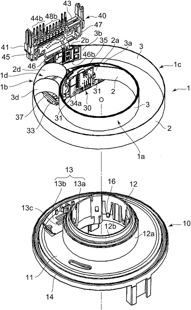
[0089] Below, based on Figure 1 to Figure 8 , The structure of the rotary connector 100 and its assembly process will be described in sequence. Figure 7 with Figure 8 The assembled rotary connector 100 is shown in FIG.

[0090]

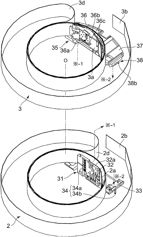
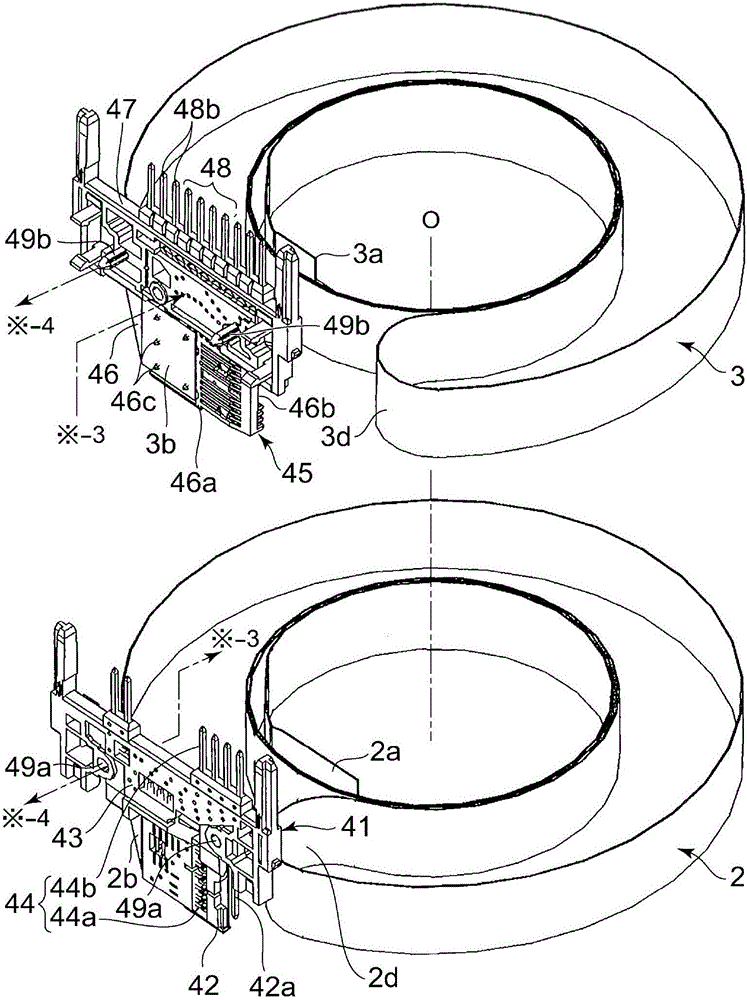
[0091] figure 1 The cable structure 1 is shown in FIG. The cable structure 1 combines the first cable 2 and the second cable 3. The first cable 2 and the second cable 3 are ribbon cables (flat cables), and the first cable 2 and the second cable 3 have a plurality of conductors (conductor parts) extending parallel to the length of the cable and insulation covering the conductors Resin layer. The first cable 2 and the second cable 3 overlap so that the width direction coincides.

[0092] in figure 1 The outer peripheral surface 12a of the cylindrical portion 12 formed on the rotating body 10 shown and Figure 4 Between the inner peripheral surface 22 of the lower housing 20 shown, there is formed Figure 5 In the ring-shaped wiring space S shown, the c...


PUM


Abstract

The present invention provides a rotary connector capable of easily accommodating a plurality of cables in a wiring space. A first cable (2) and a second cable (3) are contained in an overlapping manner; a movable inner side block (31) fixed on the first cable (2) is stacked with a movable outer side block (35) fixed on the second cable so as to form a movable side wiring block (30); a fixed outer side block (41) fixed on the first cable is stacked with a fixed inner side block (45) fixed on the second cable so as to form a fixed side wiring block (40). The movable side wiring block (30) and the fixed side wiring block (40) are assembled, so the rotary connector with the plurality of cables can be easily assembled.

Description

Technical field [0001] The present invention relates to a rotary connector installed in a steering device or the like of an automobile. The rotary connector is a rotary connector in which a plurality of ribbon-shaped cables are accommodated in a wiring space between a housing and a rotating body installed inside. Background technique [0002] Patent Document 1 describes a rotary connector installed in a steering device of an automobile. [0003] In this rotary connector, a movable side housing is rotatably combined inside a fixed side housing, and a flat cable is accommodated in a ring-shaped cable housing portion formed between the two housings. Two first lead blocks are fixed to the fixed-side housing, and one second lead block is fixed to the movable-side housing. Each lead block has an insulating holding member and a plurality of terminals held by the holding member. [0004] The fixed side end of the flat cable is divided into two, and each of the separated ends is fixed to th...

Claims


Application Information

Patent Timeline
Patent Type & Authority Applications(China)
IPC IPC(8): H01R35/02
CPCH01R35/025H01R2201/26
Inventor 对马光男朝仓俊晃稲田裕二
Owner ALPS ALPINE CO LTD
Why Eureka
Eureka Blog
Learn More