Capacitive coupling plasma diagnosis apparatus and diagnosis method

A plasma and capacitive coupling technology, applied in the direction of plasma, electrical components, etc., can solve the problems of unable to monitor and observe the discharge state, large interference of discharge electrodes, and relatively large limitations of diagnostic methods, so as to achieve the discharge effect conveniently and avoid Interfering, easy-to-use effects

Active Publication Date: 2018-08-03
HOHAI UNIV
View PDF9 Cites 3 Cited by
  • Summary
  • Abstract
  • Description
  • Claims
  • Application Information

AI Technical Summary

Problems solved by technology

[0006] However, the existing capacitively coupled plasma diagnostic devices have the following disadvantages: the device is complex, the discharge electrode is greatly disturbed by the metal cavity, and the diagnostic

Method used


Image

  • Capacitive coupling plasma diagnosis apparatus and diagnosis method
  • Capacitive coupling plasma diagnosis apparatus and diagnosis method

Examples


Example Embodiment

[0043] The following describes the present invention in detail with reference to the drawings and specific embodiments.

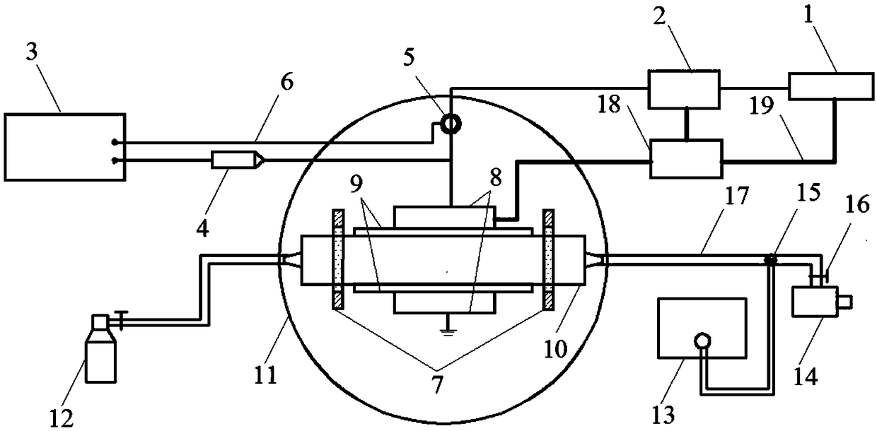
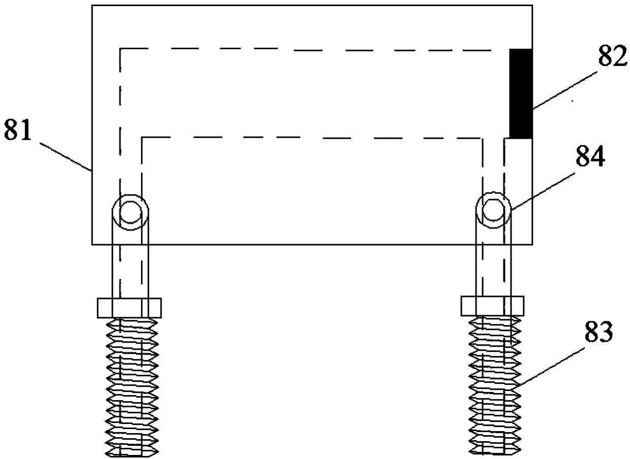
[0044] A capacitively coupled plasma diagnostic device, including a radio frequency power supply 1, a radio frequency power supply 1, a matching device 2, an oscilloscope 3, a high voltage probe 4, a current loop 5, a wire 6, a fixed bracket 7, a discharge electrode 8, a glass medium 9, and a glass cavity Body 10, circular base 11, gas cylinder 12, vacuum gauge 13, vacuum pump 14, three-way valve 15, fine-tuning valve 16, air pipe 17, water cooler 18, water pipe 19, gas filling port, and exhaust port 21.

[0045] The radio frequency power supply 1 and the radio frequency power supply 1 matcher 2 connected in series supply power to the discharge electrode 8 through the wire 6.

[0046] The oscilloscope 3 is connected to the discharge electrode 8 through the high-voltage probe 4 and the current loop 5.

[0047] The water cooler 18 is connected to the radio frequency ...


PUM


Abstract

The invention discloses a capacitive coupling plasma diagnosis apparatus and diagnosis method. The diagnosis apparatus comprises a power supply unit, a current voltage data sampling unit, a dischargeunit and an air channel; the discharge unit comprises discharge electrodes positioned on the two sides of the air channel; the power supply unit supplies power for the electrodes; the current voltagedata sampling unit detects the current and the voltage of the electrodes; the current voltage data sampling unit comprises an oscilloscope and performs detection through a current ring and a high-voltage probe; the power supply unit comprises a radio frequency power supply with a matcher; and the air channel is a glass cavity body and the electrodes are tightly attached to the two sides of the glass cavity. The other parts, except the discharge electrodes which are conductive metal, of the whole discharge unit are all insulating medium, so that interference of other metals to discharge plasmais avoided; in addition, the apparus can be directly applied to a non-intrusive mode diagnosis method; and the diagnosis apparatus has a simple structure, relatively independent parts, convenience inuse, convenience and high efficiency in discharge effect optimization by improving the parts, low manufacturing and maintenance costs, highly prolonged service life, quite high practicability and highapplicability.

Description

technical field [0001] The invention relates to a diagnostic device and a diagnostic method, in particular to a capacitive coupling plasma diagnostic device and a diagnostic method. Background technique [0002] RF capacitive coupling discharge refers to applying a voltage on two parallel electrodes separated by an air gap, so that the gas in the air gap breaks down to form a large number of electrons, ions and neutral particles, and these three particles form particles through random motion Collection, this kind of collection constitutes the plasma macroscopically. RF capacitively coupled plasma is widely used in the fields of microelectronics industry production, semiconductor chip etching and thin film technology, aviation stealth technology, biomedicine and the environment. [0003] Because radio frequency capacitive coupling discharge can generate uniform plasma in parallel and symmetrical electrode gaps, capacitive coupling discharge plasma has been widely used in sem...

Claims


Application Information

Patent Timeline
IPC IPC(8): H05H1/00H05H1/46
CPCH05H1/0081H05H1/46H05H1/466
Inventor 何湘刘冲朱寒庞佳鑫杨惠张积利陈秉岩张开骁
Owner HOHAI UNIV
Why Eureka
Try Eureka