
Apparatus for preventing displacement of retainer

a technology of retainer and preventing adsorption, which is applied in the direction of dynamo-electric converter control, multiple dynamo-motor starters, and gearing, etc., can solve the problems of affecting positioning accuracy, straightness, etc., and the maintenance of a retainer needs a considerable time, so as to secure prevent the displacement of the retainer and maintain the relative position of the retainer

Active Publication Date: 2008-05-01
TOSHIBA MASCH CO LTD
View PDF10 Cites 4 Cited by
  • Summary
  • Abstract
  • Description
  • Claims
  • Application Information

AI Technical Summary

Benefits of technology

[0016]It is therefore an object of the present invention to provide a novel apparatus for preventing displacement of a retainer, which solves the above problems in the prior art, improves the conventional technique for preventing displacement of a retainer by utilizing its property of moving half the moving distance of a table, and can securely prevent a moving object from partly sliding off a retainer.
[0018]In a preferred embodiment of the present invention, the displacement regulator comprises the stoppers for contact with the front and rear ends of each retainer disposed on each guide surface, stopper holding members which hold the stoppers, and a structure for keeping the distance between the stoppers approximately the same as the length of the retainer and maintaining symmetry of all the stoppers.
[0019]According to the present invention, the displacement regulator can be moved at a velocity which is one-half of the velocity of a moving object, such as a table. This makes it possible to maintain constant relative positions of the retainers with respect to the moving object while regulating the positions of the retainers by the stoppers, thus securely preventing displacement of the retainers.

Problems solved by technology

Such displacement gradually increases as the movement of the table 3 is repeated and, when the table 3 has a long stroke, it is possible that the table 3 may partly slide off the retainer 1 or 2, which could cause an accident.
The repair of a retainer needs a considerable time.
The displacement correction method, which involves causing the displaced retainer 1 or 2 to collide against the stopper 10, may cause deformation of the retainer, thus adversely affecting the positioning accuracy, straightness, etc. of the machine.

Method used


Image

  • Apparatus for preventing displacement of retainer
  • Apparatus for preventing displacement of retainer
  • Apparatus for preventing displacement of retainer

Examples


Embodiment Construction

[0025]A preferred embodiment of the present invention will now be described with reference to the drawings.

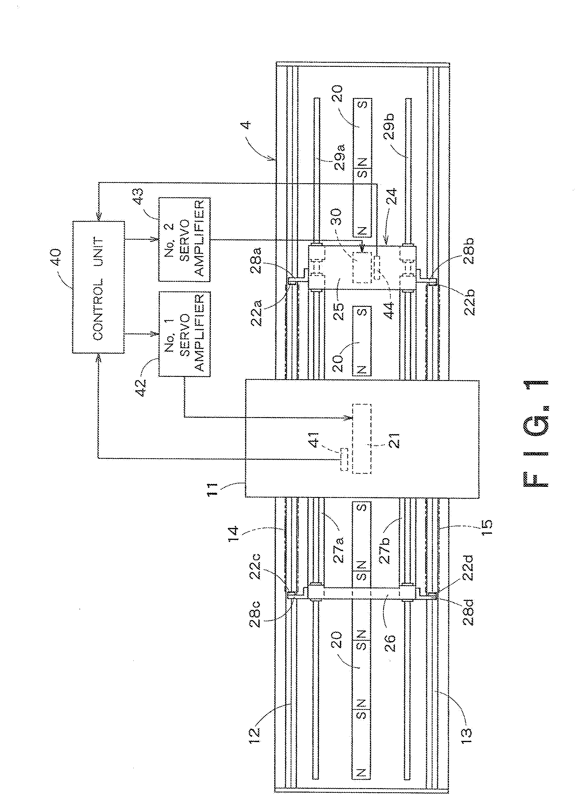
[0026]FIG. 1 is a plan view of an apparatus for preventing displacement of a retainer according to an embodiment of the present invention, which apparatus is applied to a feed guide apparatus for a table of a machine tool.

In FIG. 1, reference numeral 4 denotes a bed and reference numeral 11 denotes a table. The bed 4 has guide surfaces 12, 13 for guiding the movement of the table 11 in the long direction of the bed 4. A retainer 14, a constituent of a rolling guide, is laid on the guide surface 14, and a retainer 15 is laid on the guide surface 13.

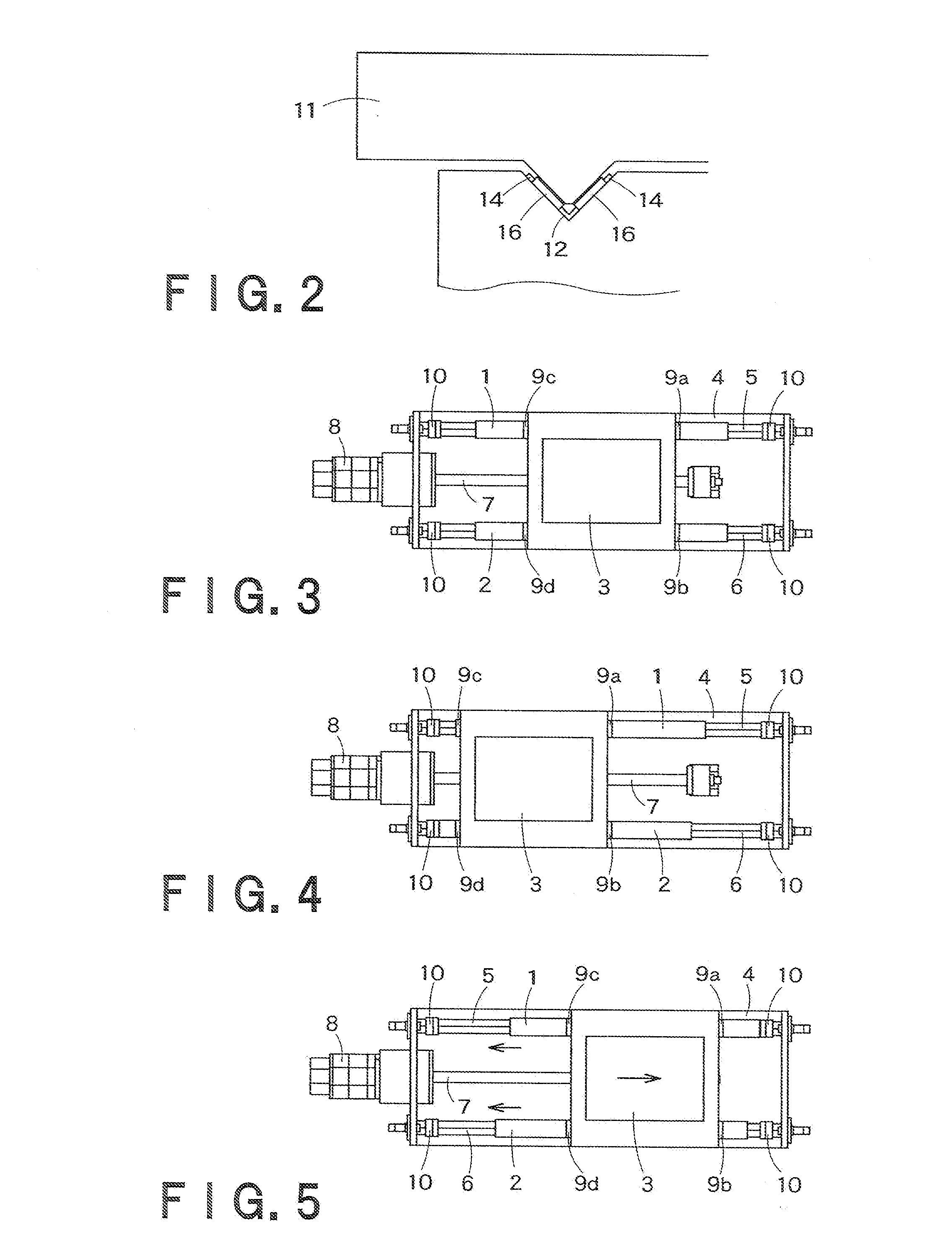
[0027]As shown in FIG. 2, in this embodiment the guide surfaces 12, 13 each have the shape of a V-shaped groove, and the both inclined surfaces of each groove serve as roller-rolling surfaces on which a large number of rollers 16 roll. The retainers 14, 15 are holders which each hold the rollers 16 in V-shaped lines conforming to the ...


PUM


Abstract

There is provided an apparatus for preventing displacement of a retainer in a rolling guide by making use of the property of the retainer of moving half the distance of a moving object, such as a table. The apparatus for preventing displacement of a retainer in a guide apparatus having a plurality of finite rollers held by retainers and including a guide mechanism for guiding the movement of a moving object of a machine tool along guide surfaces of a bed or a saddle, and a linear motor feed mechanism for feeding the moving object, includes: a displacement regulator having a stopper for regulating the position of each retainer, the regulator being movable in conjunction of the movement of the moving object; a line of magnet plates of a linear motor for driving of the moving object, the line of magnetic plates being a constituent of a linear motor feed mechanism for the moving object and being arranged parallel to the guide surfaces; a linear motor mechanism for moving the displacement regulator in the same direction as the moving direction of the moving body; and a linear motor control means for moving the displacement regulator in synchronization with the movement of the moving object at a velocity which is one-half of the velocity of the moving object.

Description

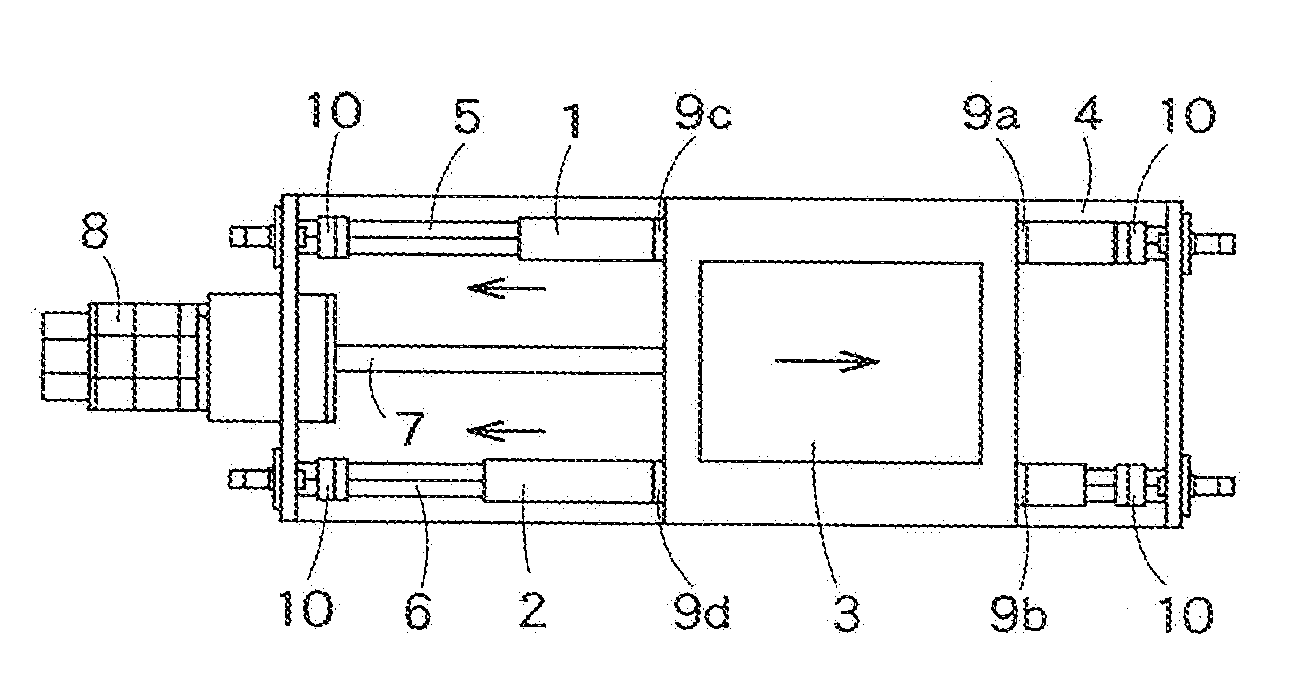
BACKGROUND OF THE INVENTION[0001]1. Field of the Invention[0002]The present invention relates to a technique which is applicable to a rolling guide apparatus for guiding a moving object, such as a table, in a machine tool, in particular a guide apparatus of the type that employs finite rollers held by a retainers and which can effectively prevent displacement of the retainer.[0003]2. Background Art[0004]Precision processing machines conventionally utilize rolling guides for guide of a moving object, such as a table or a saddle. Such rolling guides include the type of guide which uses a plurality of finite rollers held on a flat or V-shaped guide surface by means of a retainer.[0005]A moving object on finite rollers is driven to move by a ball screw. Rolling guides using finite rollers, because of their low friction and high movement precision, are used as guides for ultra-precision feeding.[0006]FIGS. 3 through 5 illustrate a change in the relative positions of retainers with respec...

Claims


Application Information

Patent Timeline
IPC IPC(8): F16H25/20F16C19/50H02K41/02F16C33/30
CPCF16C29/001F16C29/008H02K41/03F16C29/063F16C33/306F16C29/04B23Q5/22
Inventor AKIYAMA, TAKANOBU
Owner TOSHIBA MASCH CO LTD
Learn More