Antenna device

a technology of antenna array and antenna, which is applied in the field of antenna devices, can solve the problems of difficulty in realizing symmetry or simplicity of a system, and achieve the effect of maintaining uniformity of a feeding phase and increasing design and manufacturing efficiency

Active Publication Date: 2020-09-24
JAPAN AEROSPACE EXPLORATION AGENCY +1
View PDF0 Cites 4 Cited by
  • Summary
  • Abstract
  • Description
  • Claims
  • Application Information

AI Technical Summary

Benefits of technology

[0012]According to the present invention, it is possible to realize an antenna device which can increase efficiency of design and manufacture. Further, it is p

Problems solved by technology

However, when the number of antenna elements in the high-frequency feeding circuit is

Method used


Image

  • Antenna device
  • Antenna device
  • Antenna device

Examples


Embodiment Construction

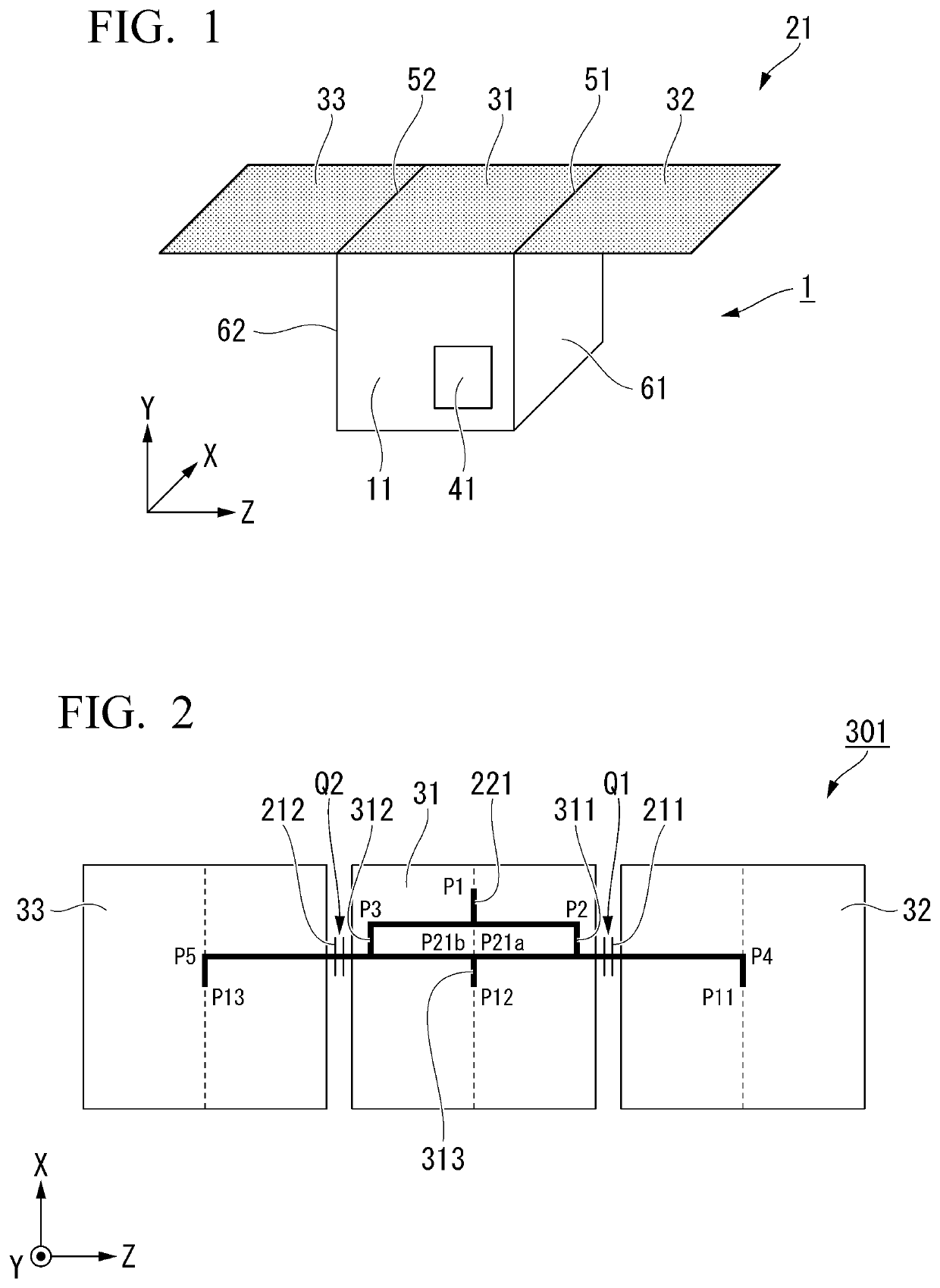
[0031]Hereinafter, embodiments of the present invention will be described with reference to the drawings.

[0032]In the following, for convenience of description, XYZ coordinate axes which are three-dimensional orthogonal coordinate systems will be described with arrows in the drawings.

[0033]Further, in the following, for convenience of description, the term “electromagnetic wave” will be used, but in general, an electromagnetic wave having a frequency of 3 THz or less is also called “radio wave”.

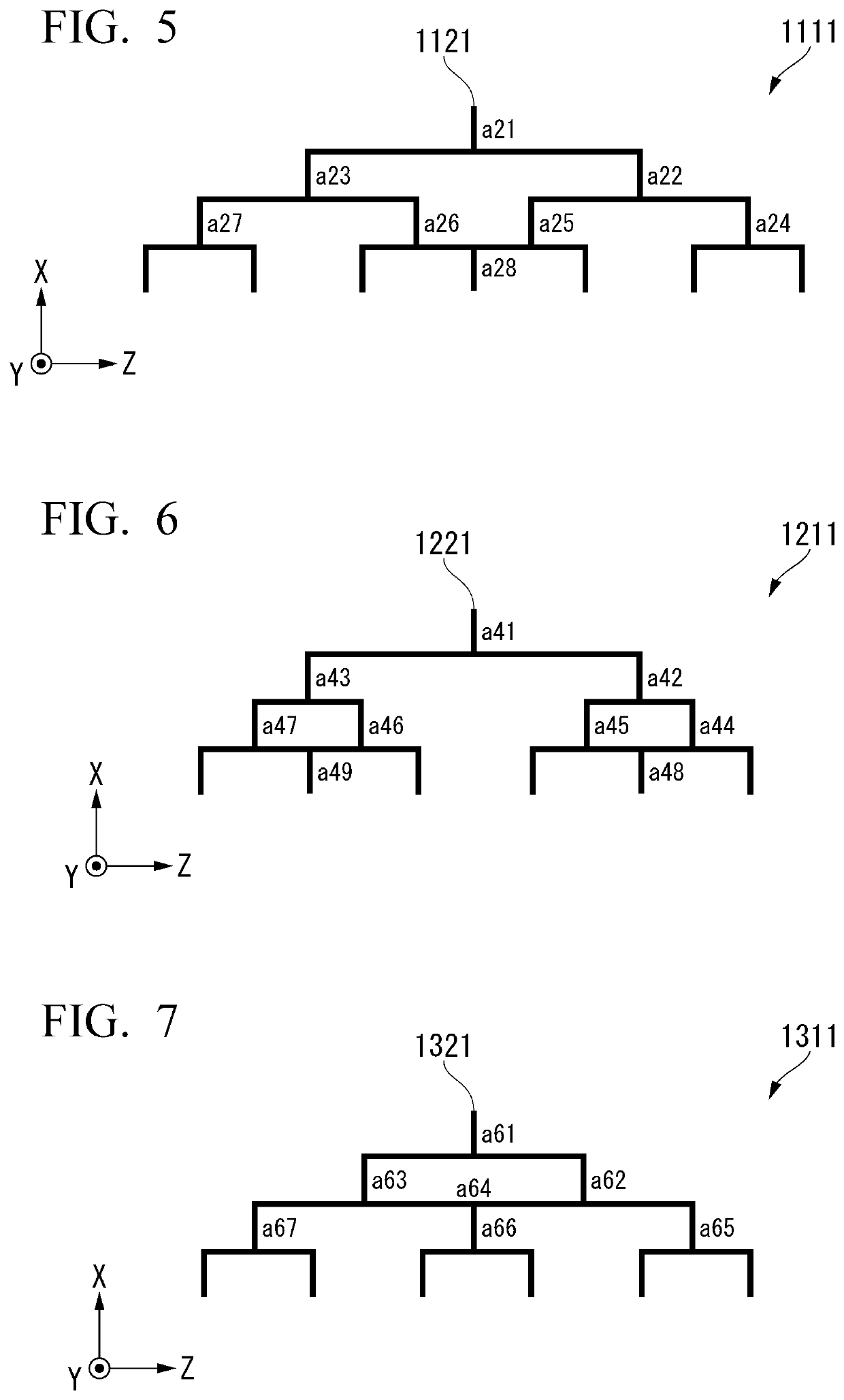
[0034]Further, in the following, for convenience of description, in a tournament-type feeding circuit, a stage in which the number of a plurality of waveguide paths are combined to be ½ in a direction from a bottom layer to a top layer will be referred to as a “layer”. In this case, for example, an r-th layer has 2k−r waveguide paths wherein r=1 to k.

[0035]Further, conversely, in the tournament-type feeding circuit, a stage in which one waveguide path is made into two in a direction from the ...


PUM


Abstract

An antenna device includes: an antenna panel; one input terminal through which a high-frequency signal is input; and a feeding circuit which distributes the high-frequency signal input to the input terminal to a plurality of antenna elements provided on the antenna panel. The feeding circuit includes: at least one first-stage branch circuit which includes one input and two outputs; at least two second-stage branch circuits which receive outputs of the first-stage branch circuit and include one input and two outputs; and a combining circuit which includes two inputs and one output and receives two outputs selected from the outputs of the first-stage branch circuit and outputs of the second-stage branch circuit.

Description

BACKGROUND OF THE INVENTIONField of the Invention[0001]The present invention is an antenna device.[0002]Priority is claimed on Japanese Patent Application No. 2019-050433, filed Mar. 18, 2019, the content of which is incorporated herein by reference.Description of Related Art[0003]There is a case in which a deployable phased array antenna is mounted on an artificial satellite as a deployable antenna device (for example, refer to Japanese Unexamined Patent Application, First Publication No. 2012-90253, which is hereinafter referred to as Patent Document 1). The deployable phased array antenna disclosed in Patent Document 1 includes a hinge which connects adjacent panels. The hinge has, for example, a degree of freedom of rotation of 90 degrees or 180 degrees.[0004]In general antenna devices, passive array antennas are used in addition to active array antennas.[0005]Generally, in a passive array antenna which requires a wide operating frequency range (broadband), a high-frequency phas...

Claims


Application Information

Patent Timeline
IPC IPC(8): H01Q1/28H01Q21/00H01Q13/02H01Q1/08H01Q21/06
CPCH01Q1/08H01Q13/0266H01Q21/061H01Q1/288H01Q21/0006H01P1/042
Inventor SAITO, HIROBUMIPYNE, BUDHADITYAHIROKAWA, JIRO
Owner JAPAN AEROSPACE EXPLORATION AGENCY
Why Eureka
Try Eureka