Methods of configuring a wing tip device on an aircraft

a technology of a wing tip and an aircraft, which is applied in the direction of wing adjustment, drag reduction, etc., can solve the problem of effectively limited maximum aircraft span, and achieve the effect of reducing lift coefficient and improving performance of aircraft for landing

Active Publication Date: 2017-12-28
AIRBUS OPERATIONS LTD
View PDF0 Cites 5 Cited by
  • Summary
  • Abstract
  • Description
  • Claims
  • Application Information

AI Technical Summary

Benefits of technology

[0008]The aircraft compatibility limit is preferably a gate limit. The prior art already recognises that a moveable wing tip device is advantageous in providing a large wing span aircraft (during flight) that can still comply with airport compatibility gate limits on the ground. The present invention recognises that a moveable wing tip device can then also be used to facilitate additional advantages; namely that it can be used in a plurality of different configurations that are each tailored to different parts of the flight regime. Aspects of the present invention recognise that the performance of the aircraft can be better tailored for take-off by configuring the wing tip device into the take-off configuration (in which it has a high-lift coefficient), and then better tailored for another flight condition (such as climb) by configuring the wing tip device in flight configuration (in which it has a lower lift coefficient).
[0018]It will be appreciated that the aircraft typically comprises two wings, symmetrical about the centre-line of the aircraft fuselage. Each wing preferably comprises a fixed wing and with a wing tip device moveably mounted at the outer end thereof, between the plurality of configurations. References herein to the changing of configuration of a wing tip device, may apply equally to both the wing tip devices on the aircraft (i.e. to either wing). The configurations of the wing tip devices are preferably changed in synchronisation. The configurations of the wing tip devices are preferably changed such that the wings, and the wing tip devices, maintain their symmetry. Such arrangements tend to avoid any asymmetric load or drag conditions.
[0019]According to a second aspect of the invention, there is provided a method of configuring a wing tip device on an aircraft, the aircraft comprising a wing having a fixed wing with the wing tip device moveably mounted at the outer end thereof, wherein the method comprises the steps of: (i) flying the aircraft with the wing tip device in a flight configuration, in which flight configuration the wing tip device has a second lift coefficient, (ii) moving the wing tip device to a landing configuration in which the wing tip device is moved away from the flight configuration such that the wing tip device has a first lift coefficient, the first lift coefficient being greater than the second lift coefficient; (iii) landing the aircraft at an airport with the wing tip device in the landing configuration; (iv) moving the wing tip device to a ground configuration, in which ground configuration the span of the aircraft is reduced to within the airport compatibility limit, and undertaking ground-based operations at the airport with the wing tip device in the ground configuration. This aspect of the present invention recognises that the performance of the aircraft can be better tailored for landing by configuring the wing tip device into the landing configuration (in which it has a high-lift coefficient), but better tailored for another flight condition by configuring the wing tip device in a flight configuration (in which it has a lower lift coefficient).
[0021]The wing tip device may be rotatable between the configurations about an axis of rotation. Aspects of the present invention have been found to be especially beneficial in arrangement in which the wing tip device is moveable between the configurations by rotation about an axis which is oriented perpendicular to an oblique cut plane separating the wing tip device and the fixed wing. Such an arrangement may provide a continuous range of movement and is therefore especially useful when moving the wing tip device between multiple configurations. It is also especially beneficial in embodiments in which it is desirable for the wing tip device to have a different sweep angle and / or angle of attack in the different configurations, because such an orientation of axis tends to inherently alter the sweep angle as the wing tip device is rotated.

Problems solved by technology

However, maximum aircraft span is effectively limited by airport operating rules that govern various clearances required when manoeuvring around the airport (such as span and / or ground clearance required for gate entry and safe taxi usage).

Method used


Image

  • Methods of configuring a wing tip device on an aircraft
  • Methods of configuring a wing tip device on an aircraft
  • Methods of configuring a wing tip device on an aircraft

Examples


Embodiment Construction

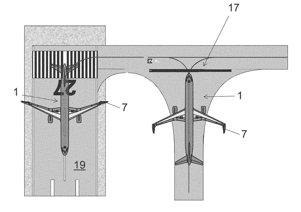
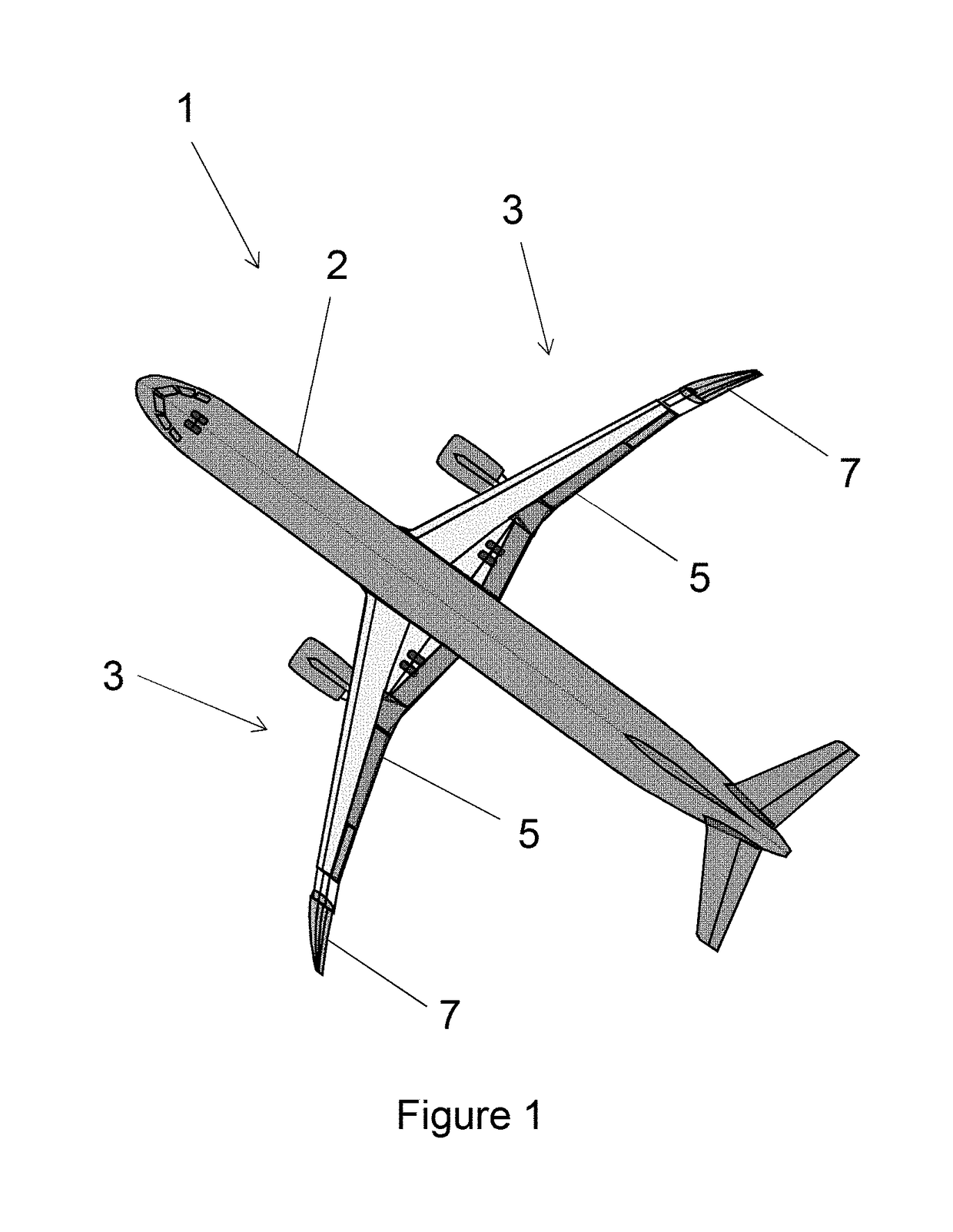
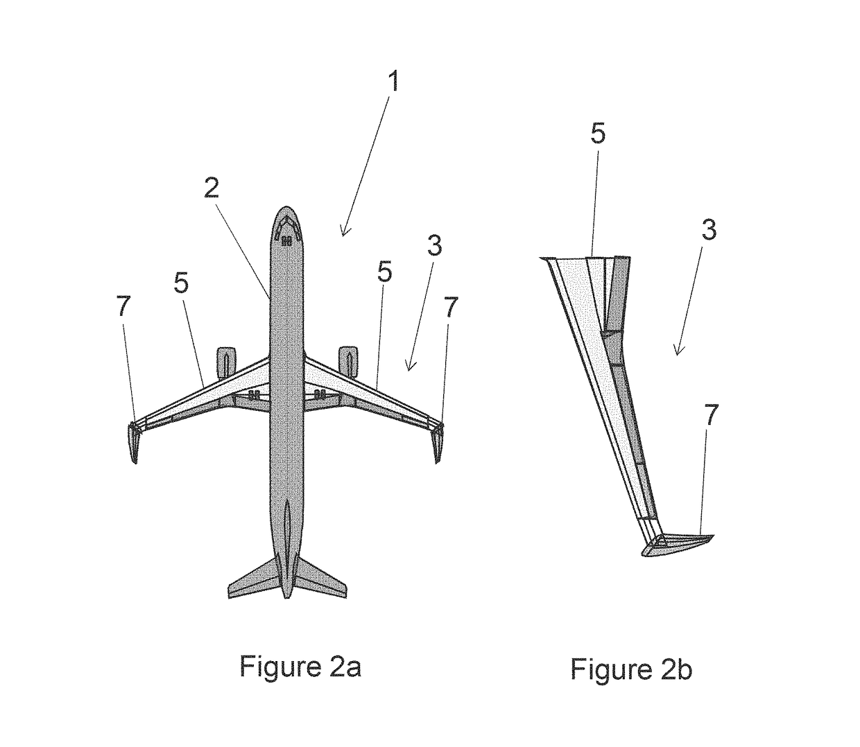
[0040]FIG. 1 is a plan view of an aircraft 1 according to a first embodiment of the invention. The aircraft 1 comprises a two wings 3 positioned symmetrically on either side of the aircraft fuselage 2. Each wing 3 comprises a fixed inner wing 5, and wing tip device 7 (shown as a shaded component for the sake of clarity) mounted at the outer end 5a thereof. Hereinafter, reference is often made to one of the wings / wing tip devices, but it will be appreciated that the description applies to both wing tip devices 7 on the aircraft 1.

[0041]The wing tip device 7 is mounted on a joint that allows the wing tip device 7 to rotate relative to the fixed wing 5. In the first embodiment of the invention, the wing tip device 7 and the fixed wing 5 are separated along an oblique cut plane passing through the upper and lower surfaces of the wing. The wing tip device 7 is rotatable about an axis that extends in a direction perpendicular to the oblique cut plane. Such a joint is described in WO2015 / 1...


PUM


Abstract

A method of configuring a wing tip device (7) on an aircraft (1), including: undertaking ground-based operations at an airport with the wing tip device (7) in a ground configuration, in which the span of the aircraft is within an airport compatibility limit, moving the wing tip device (7) to a take-off configuration in which the wing tip device (7) is moved away from the ground configuration such that the span of the aircraft is increased and such that the wing tip device (7) has a first lift coefficient; taking-off with the wing tip device (7) in the take-off configuration; moving the wing tip device from the take-off configuration to a flight configuration, in which the wing tip device has a second lift coefficient, the second lift coefficient being lower than the first lift coefficient. The lift coefficient may be changed by adjusting the sweep of the wing tip device (7).

Description

FIELD OF THE INVENTION[0001]The present invention relates to methods of configuring a moveable wing tip device on an aircraft, especially for take-off and / or landing of the aircraft. The present invention also relates to an aircraft for use in such a method.BACKGROUND OF THE INVENTION[0002]There is a trend towards increasingly large passenger aircraft with higher performance efficiency (for example fuel burn reduction). It is desirable for these aircraft to have correspondingly large wing spans, in order to maximise performance efficiency. However, maximum aircraft span is effectively limited by airport operating rules that govern various clearances required when manoeuvring around the airport (such as span and / or ground clearance required for gate entry and safe taxi usage).[0003]To address this problem, various arrangements comprising moveable wing tip devices, that specifically enable the span to be reduced in a ground configuration, have been suggested. US2013 / 0099060 and WO2015...

Claims


Application Information

Patent Timeline
Patent Type & Authority Applications(United States)
IPC IPC(8): B64C3/56B64C3/58B64C3/40
CPCB64C3/56B64C3/40B64C3/58Y02T50/10
Inventor THOMPSON, ROBERT IANWILLIAMS, GEOFFREY RICHARDLIVINGS, NICHOLASNICHOLLS, KEVIN
Owner AIRBUS OPERATIONS LTD
Why Eureka
Try Eureka