Air handling in a heavy-duty opposed-piston engine

A technology of opposed piston and engine, applied in the direction of internal combustion piston engine, reciprocating piston engine, engine components, etc., can solve the problems of increasing pumping loss and reducing thermal efficiency of engine braking.

Inactive Publication Date: 2018-08-03
ACHATES POWERS INC
View PDF8 Cites 3 Cited by
  • Summary
  • Abstract
  • Description
  • Claims
  • Application Information

AI Technical Summary

Problems solved by technology

A supercharger is normally used to move charge air to the engine intake port fast enough to maintain the scavenging ratio, but ru...

Method used


Image

  • Air handling in a heavy-duty opposed-piston engine
  • Air handling in a heavy-duty opposed-piston engine
  • Air handling in a heavy-duty opposed-piston engine

Examples


Embodiment Construction

[0025] In this disclosure, "fuel" is any fuel that can be used in an opposed piston engine. The fuel may be a relatively homogeneous composition or blend. For example, the fuel may include diesel fuel, natural gas, gasoline, or another equivalent fuel ignitable by compression, ignition, and / or spark ignition. Further, the description contemplates ignition caused by the compressed air / fuel mixture; however, in some instances, it may be desirable to provide additional mechanisms, such as glow plugs, spark plugs, pilot injection, or laser circuits, to assist in compression ignition.

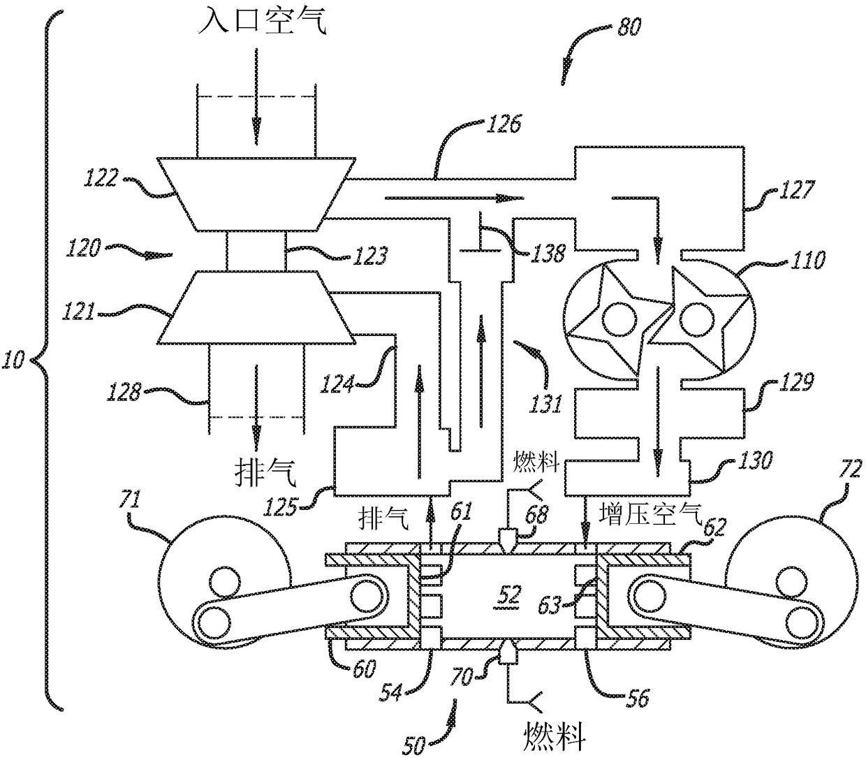
[0026] According to the present disclosure, when the piston is at or near the TDC position, fuel is injected into the compressed air in the combustion chamber formed between the end surfaces of the opposed pistons. In other aspects, injection may occur earlier in the compression stroke shortly after both ports are closed. The air is preferably pressurized ambient air; however, it may include other...


PUM


Abstract

An air handling arrangement in a two-stroke cycle, opposed-piston engine with uniflow scavenging and constructed for heavy-duty operation includes sequentially arranged turbochargers in series with asupercharger, in some aspects, the air handling system is equipped with an EGR channel.

Description

[0001] priority [0002] This application claims priority to U.S. Provisional Patent Application No. 62 / 264,022, filed December 7, 2015, and U.S. Provisional Application No. 62 / 279,284, filed January 15, 2016. [0003] related application [0004] This application incorporates commonly-owned U.S. Patent Application 14 / 039,856, filed September 27, 2013, published as US 2014 / 0026563, and filed February 11, 2015 claiming December 2, 2014 Subject matter related to the subject matter of commonly-owned PCT application US2015 / 015365 of priority to US 61 / 939,170. technical field [0005] The field is a two-stroke cycle direct-flow scavenged opposed-piston engine. More specifically, the present application relates to air treatment for opposed-piston engines by means of a multi-stage arrangement of turbochargers placed in series with a supercharger to provide a variable flow rate of charge air with minimal pumping losses. flow. Background technique [0006] A two-stroke cycle engi...

Claims


Application Information

Patent Timeline
IPC IPC(8): F02B25/08F02B75/02F02B39/10F02B33/34F02B37/00F02B37/013F02B37/04F02B37/12F02B37/16F02B37/18F02B75/28F01B7/02F02M26/08F02M26/09
CPCF02B33/34F02B37/004F02B37/013F02B37/04F02B37/16F02B37/18F02B39/10F01B7/02F02B75/282F02B2075/025F02M26/08F02M26/09F01B7/14F02B37/162F02B25/08Y02T10/12F02D41/0007F02D2200/04F02D2200/101
Inventor G·雷格纳M·姜
Owner ACHATES POWERS INC
Why Eureka
Try Eureka