Check patentability & draft patents in minutes with Patsnap Eureka AI!

Positioning system for a motor vehicle, motor vehicle and method

A positioning system, a technology for motor vehicles, applied in satellite radio beacon positioning systems, radio wave measurement systems, and the use of re-radiation, etc., can solve problems such as low signal quality

Active Publication Date: 2019-09-03
AUDI AG
View PDF10 Cites 0 Cited by
  • Summary
  • Abstract
  • Description
  • Claims
  • Application Information

AI Technical Summary

Problems solved by technology

[0008] However, this method has the disadvantage that it relies on existing road network database correlations and is only suitable for correspondingly extended buildings, such as tunnels, in which the disconnection of the GPS signal and the associated, predetermined signal quality The low (as described in DE 10 2007 020 434 A1) is very suitable for reliable identification of entering tunnels

Method used


Image

  • Positioning system for a motor vehicle, motor vehicle and method
  • Positioning system for a motor vehicle, motor vehicle and method
  • Positioning system for a motor vehicle, motor vehicle and method

Examples


Embodiment Construction

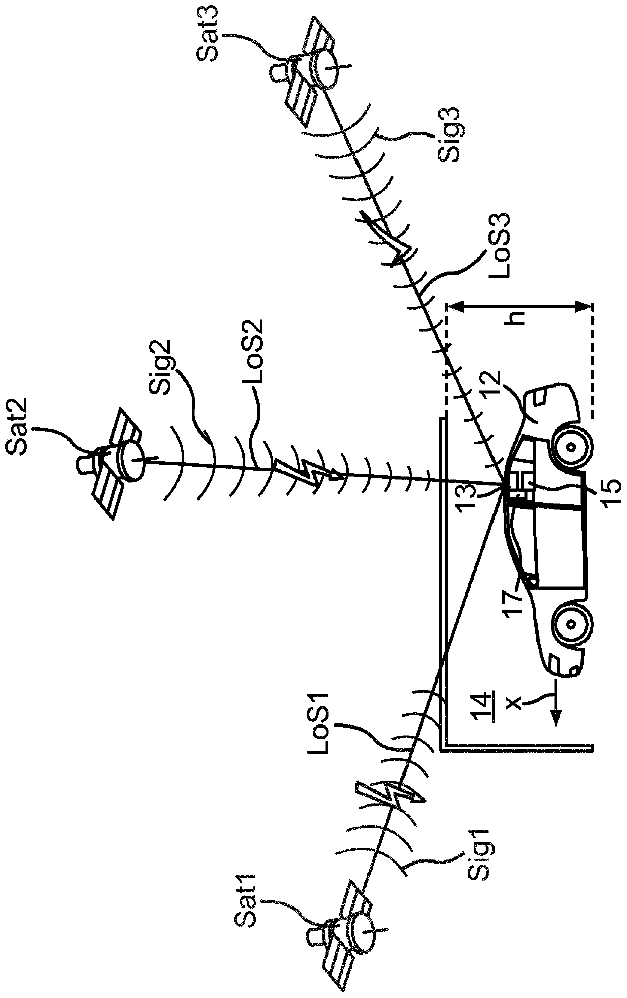
[0035] When motor vehicle 12 drives into garage 14 , motor vehicle 12 performs a driving movement x. The motor vehicle 12 has a receiver unit 13 which is designed to receive navigation signals. according to figure 1 In the view in , there are three satellites Sat1, Sat2 and Sat3 for use, wherein the first satellite Sat1 sends out the first navigation signal Sig1, the second satellite Sat2 sends out the second navigation signal Sig2, and the third satellite Sat3 sends out the third satellite signal Sig3 . A direct line between the first satellite Sat1 and the antenna of the receiving unit 13 forms a first line of sight LoS1 (English: line-of-sight), and a line between the second satellite Sat2 and the antenna forms a second line of sight LoS2. in accordance with figure 1 In the view of , the first line of sight LoS1 and the second line of sight LoS2 are interrupted, where the first navigation signal Sig1 and the second navigation signal Sig2 are respectively blocked by the r...


PUM


Abstract

The invention relates to a positioning system for a motor vehicle (12) for determining whether the motor vehicle is in an area (14, 24) covered by a roof element of a building, said positioning system comprising: a receiving unit ( 13), the receiving unit is designed to receive navigation signals (Sig1, Sig2, Sig3, Sig4) of multiple satellites (Sat1, Sat2, Sat3, Sat4) of one or more global satellite navigation systems and obtain corresponding The temporal variation of the signal strength of the navigation signal. An evaluation unit (15) is provided, which is designed to determine the line of sight (LoS1, LoS2, LoS3, LoS4) from the motor vehicle to the corresponding satellite whose navigation signal is received, based on the correspondingly determined line of sight pair The temporal variation of the signal strength of the corresponding navigation signal is evaluated, and by associating the driving movement (x) of the motor vehicle with the corresponding line of sight, it is determined that the motor vehicle has entered the covered area. Furthermore, the invention relates to a motor vehicle (12) having such a positioning system. Furthermore, the invention relates to a corresponding method.

Description

technical field [0001] The invention relates to a motor vehicle locating system for determining whether a motor vehicle is in an area covered by a roof element of a building. Furthermore, the invention relates to a motor vehicle with such a positioning system. Furthermore, the invention relates to a method for determining whether a motor vehicle is located in an area covered by a roof element of a building. Background technique [0002] So far, Global Navigation Satellite System (GNSS) is mainly used for navigation and positioning. In principle, such a system is based on the transit time measurements of different satellites. At least four satellites must be visible at any one time to reliably unambiguously locate. Here, the receiver can determine its own position from the positions of the satellites and the signal propagation times. [0003] To detect roofs, ie roofs, distance-sensing sensors are usually used which are oriented upwards and can thus directly determine whe...

Claims


Application Information

Patent Timeline
Patent Type & Authority Patents(China)
IPC IPC(8): G01S19/14G01S19/39
CPCG01S19/14G01S19/393G01C21/206G01S11/06G01S19/42
Inventor F·舒勒F·豪贝尔
Owner AUDI AG
Features
  • R&D
  • Intellectual Property
  • Life Sciences
  • Materials
  • Tech Scout
  • Unparalleled Data Quality
  • Higher Quality Content
  • 60% Fewer Hallucinations
Learn More