Wiper device especially for the panes of motor vehicles

a technology for windshields and motor vehicles, applied in vehicle maintenance, vehicle cleaning, domestic applications, etc., can solve the problems of high cost of disposition and embodiment of such securing means

Inactive Publication Date: 2005-06-28
ROBERT BOSCH GMBH
View PDF12 Cites 59 Cited by
  • Summary
  • Abstract
  • Description
  • Claims
  • Application Information

AI Technical Summary

Benefits of technology

[0011]So that the extension of the pivot bolt, which may protrude by a portion thereof from the countersunk feature, will not present any risk of injury to a person working with the wiper blade, for instance when cleaning the windshield by hand, the depth of the countersunk feature is at least as great as the height of the extension, measured in the direction of the pivot axis.
[0012]An especially economical embodiment of the concept of the invention is attained by providing that the extension is embodied on the order of a rectangular plate, one long side of which faces toward the pivot bolt and is joined, crossing the pivot axis, to the pivot bolt, preferably integrally, and its length is greater than the diameter of the pivot bolt. At the two places where the extension protrudes past the diameter of the pivot bolt, one securing face of the wiper arm can then be embodied in a simple way.

Problems solved by technology

The disposition and embodiment of such securing means is expensive, because on the one hand the pivot bolt has to be provided with the annular groove, and on the other, when a wiper blade is replaced, the new wiper blade has to be re-equipped with a suitable leaf spring.

Method used


Image

  • Wiper device especially for the panes of motor vehicles
  • Wiper device especially for the panes of motor vehicles
  • Wiper device especially for the panes of motor vehicles

Examples


Embodiment Construction

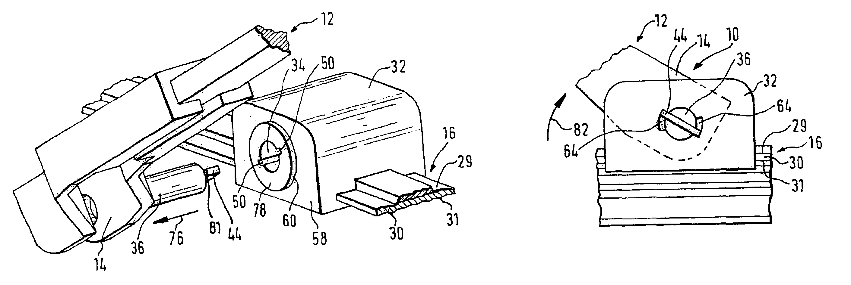
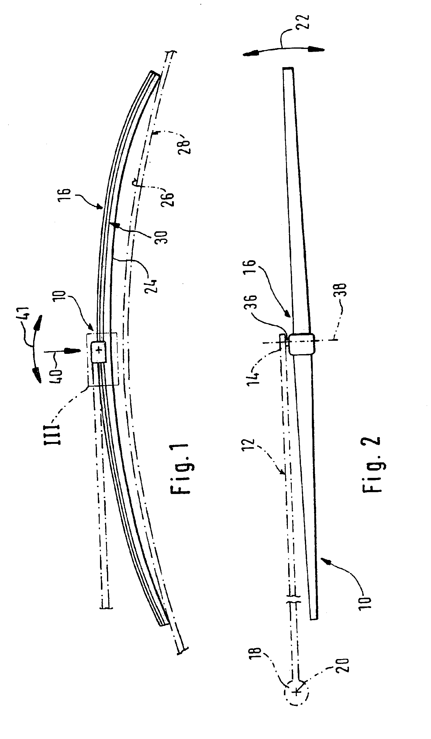
[0026]A wiper system of the invention includes a wiper lever 10 (FIGS. 1 and 2), which has a driven wiper arm 12 on one end that is guided on the motor vehicle, not shown, and to whose free end 14 an elongated wiper blade 16 is pivotably connected. The wiper arm 12 is supported by its other end 18 and can be swiveled back and forth between turning points about a pendulum axis 20 in the direction of the double arrow 22. The wiper blade 16 is moved transversely to its length across the window to be wiped, and with a rubber-elastic wiper strip 24, it presses against the surface 26 of the window 28 to be wiped.

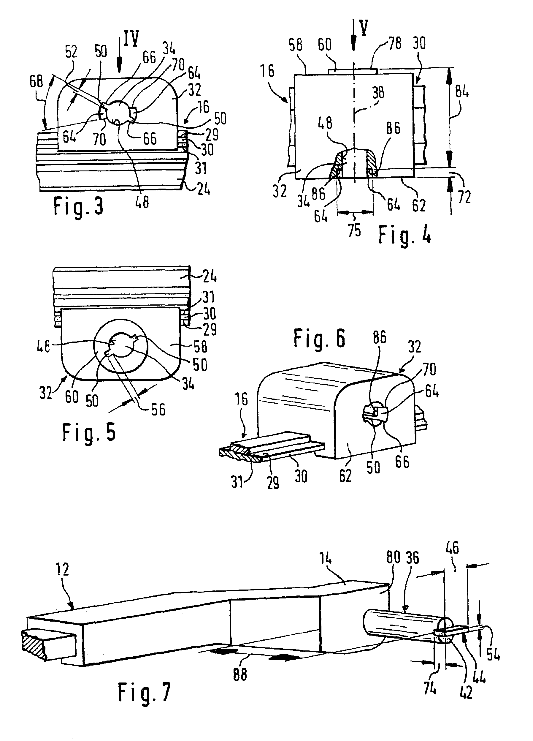
[0027]The wiper strip 24 is joined, parallel to the longitudinal axis, to a bandlike-elongated, spring-elastic support element 30, on whose upper band face 29, facing away from the window, a coupling part 32 is seated (FIG. 8), by way of which the wiper blade 16 is pivotably connected to the wiper arm 20. To that end, the coupling part 32, resting flatly on the band face 29, is pr...


PUM


Abstract

A wiper system is proposed, which is used to clean windows, in particular of motor vehicles. The wiper system has a driven wiper arm (12), guided on the motor vehicle and movable between two turning points, on whose free end (14), a pivot bolt (36) retained thereon is disposed, whose pivot axis (38) extends transversely to the longitudinal axis of the wiper arm, essentially in the direction of motion (double arrow 22) of the wiper arm (12), on which pivot bolt a wiper blade (16) is supported that can be pivoted about the pivot axis (38) and pressed against the window (28), and the wiper system has means for securing the wiper blade to the pivot bolt, which means have stop faces (78), (86) disposed on the wiper blade transversely to the pivot axis and spaced apart from one another and pointing away from one another, which fittingly engage between securing faces (80, 81), facing one another, of the wiper arm (12). A simple and economical wiper system is obtained if the stop faces of the wiper blade are disposed on the two long sides of a coupling part (32) that is present on the wiper blade and has a bearing bore (34) for the pivot bolt (36); that one securing face of the wiper arm is a cheek region (80) oriented toward the wiper blade; and that the other securing face (81) is embodied on an extension (44), protruding from the bearing bore (34), of the pivot bolt (36), which extension engages the stop face (86), facing away from the wiper arm, of the wiper blade (16) from behind.

Description

BACKGROUND OF THE INVENTION[0001]The invention is based on a wiper system. In one known wiper system of this type (German Patent Disclosure DE 10 55 410 A1), the wiper arm and the wiper blade are disposed side by side, in terms of a view toward the window to be wiped, or one after the other, in terms of the direction of operation of the wiper system. As a result, a lower structural height for the wiper system is attained than is possible ,n wiper systems in which the wiper arm is located above the wiper blade (DE 1505397 A1). The lesser structural height of the generic wiper system has advantages in terms of the behavior of the wiper blade with regard to lifting away from the window, especially at high vehicle speeds. In such a wiper system, so that the wiper blade will be secured to the pivot bolt during wiping operation, the pivot bolt disposed laterally on the wiper arm is provided in its middle portion with an annular groove, into which leaf spring, secured by one end to the wip...

Claims


Application Information

Patent Timeline
Patent Type & Authority Patents(United States)
IPC IPC(8): B60S1/32B60S1/40B60S1/38
CPCB60S1/4074B60S1/3849B60S1/40
Inventor DE BLOCK, PETERBREESCH, FRANSWIJNANTS, PETER
Owner ROBERT BOSCH GMBH
Why Eureka
Try Eureka