
Glass cement printing device

A printing device and glass glue technology, applied in printing, printing machines, rotary printing machines, etc., can solve the problems affecting the performance and service life of OLED devices, the ability to isolate water and oxygen, and the difficulty of accurately controlling the printing accuracy of glass glue, etc. , to achieve the effect of eliminating glass glue offset and edge burrs, facilitating precise control, and eliminating glass glue offset and edge burrs

Active Publication Date: 2018-08-10
BOE TECH GRP CO LTD +1
View PDF13 Cites 0 Cited by
  • Summary
  • Abstract
  • Description
  • Claims
  • Application Information

AI Technical Summary

Problems solved by technology

[0003] However, this technology is difficult to accurately control the printing accuracy of the glass glue, that is, the height and width of the glass; at the same time, the glass will appear offset and edge burrs after printing, resulting in the back-end laser sintering of the cover glass and the array substrate after lamination During the process, the effective sintering area of ​​the glass is reduced, and the ability to isolate water and oxygen is reduced, which seriously affects the performance and service life of OLED devices

Method used


Image

  • Glass cement printing device
  • Glass cement printing device

Examples


Embodiment Construction

[0026] The following will clearly and completely describe the technical solutions in the embodiments of the present invention with reference to the accompanying drawings in the embodiments of the present invention. Obviously, the described embodiments are only some, not all, embodiments of the present invention. Based on the embodiments of the present invention, all other embodiments obtained by persons of ordinary skill in the art without making creative efforts belong to the protection scope of the present invention.

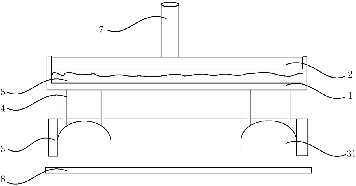
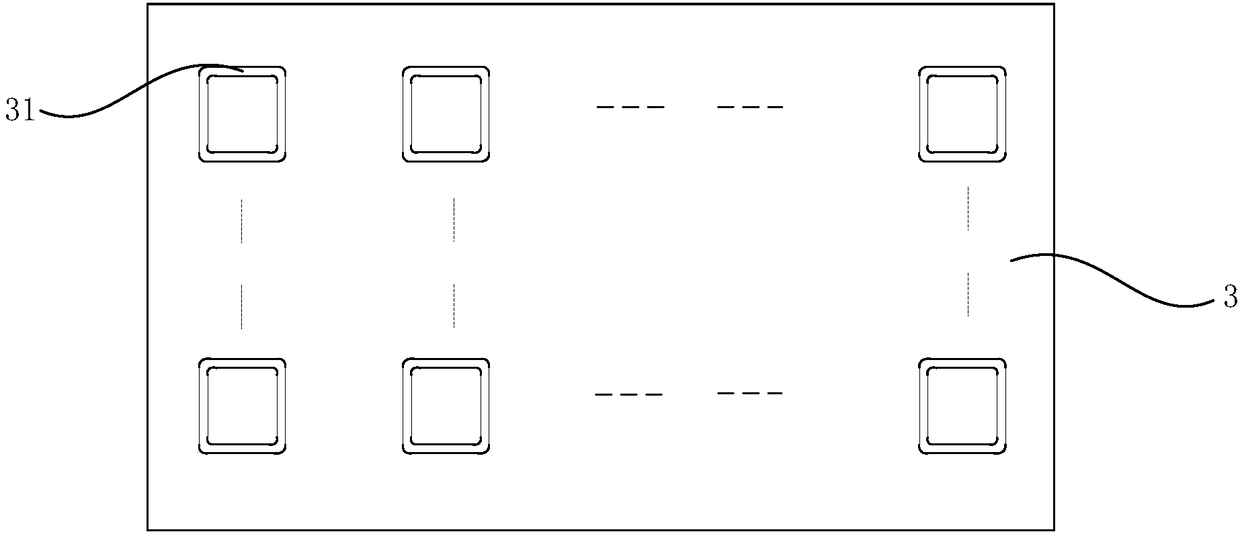
[0027] Please refer to figure 1 and figure 2 , the invention provides a glass glue printing device, comprising:

[0028] A storage box 1 with an open top, the bottom plate of the storage box 1 is provided with a plurality of glue outlets, and each glue outlet is provided with a glue delivery pipe 4;

[0029] A pressure plate 2 located in the storage box 1 and slidingly fitted with the side wall of the storage box 1, the pressure plate 2 is opposite to the b...


PUM


Abstract

The invention relates to the technical field of display, and discloses a glass cement printing device. The glass cement printing device comprises an accommodating box with a top opening, a pressure plate, and a printing plate, wherein a plurality of glue outlets are formed in a bottom plate of the accommodating box; each glue outlet is equipped with a glue conveying tube; the pressure plate is positioned in the accommodating box and is in sliding fit to the side wall of the accommodating box; the pressure plate is opposite to the bottom plate of the accommodating box, and the bottom plate andthe side walls of the accommodating box are matched to form an accommodating cavity; each glue conveying tube communicates with the accommodating cavity through the glue outlets; the printing plate isequipped with printing units which are in one-to-one correspondence to the glue outlets; each printing unit comprises a ring-shaped printing slot, an opening of which is away from the accommodating box, a gas guide hole is formed in the side wall of the printing slot, and in each pair of the mutually corresponding glue outlet and printing unit, the glue outlet communicates with the printing slotof the printing unit through the corresponding glue conveying tube. By changing the structure of the device, the glue cement printing device is not only beneficial for precisely controlling glass cement printing precision, but also can eliminate a glass cement deviation phenomenon and an edge burr phenomenon.

Description

technical field [0001] The invention relates to the field of display technology, in particular to a glass glue printing device. Background technique [0002] Currently, one of the encapsulation methods adopted by OLED (Organic Light-Emitting Diode, Organic Light-Emitting Diode) display devices is glass glue encapsulation, and the glass glue is printed on the cover glass by screen printing. [0003] However, this technology is difficult to accurately control the printing accuracy of the glass glue, that is, the height and width of the glass; at the same time, the glass will appear offset and edge burrs after printing, resulting in the back-end laser sintering of the cover glass and the array substrate after lamination During the process, the effective sintering area of ​​the glass is reduced, and the ability to isolate water and oxygen is reduced, which seriously affects the performance and service life of the OLED device. Contents of the invention [0004] The invention p...

Claims


Application Information

Patent Timeline
IPC IPC(8): B41F17/00H01L51/56
CPCB41F17/00B41P2217/50H10K71/00
Inventor 陶敏王业栋白雪飞王浩田
Owner BOE TECH GRP CO LTD
Learn More