Quickly-mountable municipal traffic barrier

A guardrail and municipal technology, applied in the municipal field, can solve the problems that the municipal guardrail does not have the advantages of quick installation, and achieve the effects of avoiding instability, improving stability and prolonging service life

Inactive Publication Date: 2018-08-14
孙利韬
5 Cites 2 Cited by

AI-Extracted Technical Summary

Problems solved by technology

[0003] Aiming at the deficiencies of the prior art, the present invention provides a municipal guardrail that can be quickly installed, which has the ...

Abstract

The invention discloses a quickly-mountable municipal traffic barrier which comprises vertical columns. Supporting legs are fixedly connected to bottoms of the vertical columns, first transverse railings are arranged at the top and the bottom of the right side of the vertical columns, second transverse railings are arranged at the top and the bottom of the left side of the vertical columns, supporting columns are arranged between the first transverse railings and between the second transverse railings, and connection pipes are fixedly connected to the top and bottom of the right side of the vertical columns. By joint use of the vertical columns, the supporting legs, the first transverse railings, the second transverse railings, the supporting columns, the connection pipes, connection blocks, supporting plates, telescopic rods, springs, connection plates, sliders, slide rails, clamping blocks, through holes and clamping grooves, the problem of failure in quick mounting of existing municipal traffic barriers is solved. In a mounting process of the quickly-mountable municipal traffic barrier, time of mounting personnel is greatly saved, traffic barrier mounting speed is increased, andaccordingly labor consumption of the mounting personnel is reduced.

Application Domain

Roadway safety arrangements

Technology Topic

Engineering

Image

  • Quickly-mountable municipal traffic barrier
  • Quickly-mountable municipal traffic barrier
  • Quickly-mountable municipal traffic barrier

Examples

  • Experimental program(1)

Example Embodiment

[0017] (In the description of the present invention, it should be understood that the terms "center", "longitudinal", "transverse", "length", "width", "thickness", "upper", "lower", "front", "Back", "Left", "Right", "Vertical", "Horizontal", "Top", "Bottom", "Inner", "Outer", "Clockwise", "Counterclockwise" and other directions indicated Or the positional relationship is based on the position or positional relationship shown in the drawings, which is only for the convenience of describing the present invention and simplifying the description, rather than indicating or implying that the pointed device or element must have a specific orientation, be constructed and operated in a specific orientation Therefore, it cannot be understood as a limitation of the present invention.
[0018] In addition, the terms "first" and "second" are only used for descriptive purposes, and cannot be understood as indicating or implying relative importance or implicitly indicating the number of indicated technical features. Thus, the features defined with "first" and "second" may explicitly or implicitly include one or more of these features. In the description of the present invention, "plurality" means two or more than two, unless specifically defined otherwise. )
[0019] The technical solutions in the embodiments of the present invention will be clearly and completely described below in conjunction with the accompanying drawings in the embodiments of the present invention. Obviously, the described embodiments are only a part of the embodiments of the present invention, rather than all the embodiments. Based on the embodiments of the present invention, all other embodiments obtained by those of ordinary skill in the art without creative work shall fall within the protection scope of the present invention.
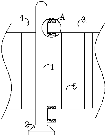
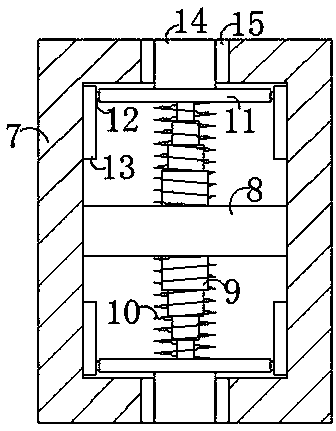
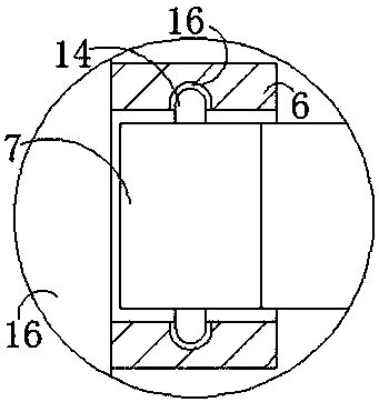
[0020] See Figure 1-3 , A municipal protective fence that can be quickly installed, including a column 1, a support leg 2 is fixedly connected to the bottom of the column 1, a fixed block is fixedly connected to the bottom of the support leg 2, and a non-slip pattern is provided on the bottom of the fixed block. The setting can play a non-slip effect on the support leg 2, avoiding the sliding of the column 1 during use, thereby improving the stability of the protective fence. The top and bottom of the right side of the column 1 are equipped with first horizontal rails. 3. The top and bottom of the left side of the column 1 are fixedly connected with a second horizontal column 4, a supporting column 5 is arranged between the first horizontal column 3 and the second horizontal column 4, the first horizontal column 3 and the second horizontal column 4 are all fixedly connected to the support column 5 by a fixing member, and the support columns 5 are arranged equidistantly, the top and bottom of the right side of the column 1 are fixedly connected with a connecting tube 6, and the inner cavity of the connecting tube 6 is provided with a connecting block 7 , And the right end of the connecting block 7 is fixedly connected with the first horizontal rail 3, the inner cavity of the connecting block 7 is fixedly connected with a support plate 8, the top and bottom of the support plate 8 are both provided with telescopic rods 9, the top and bottom of the support plate 8 Both are fixedly connected to the telescopic rod 9 by a fixing member, and the two telescopic rods 9 are arranged symmetrically with respect to the support plate 8. The surface of the telescopic rod 9 is sleeved with a spring 10, and the arrangement of the telescopic rod 9 can protect the spring 10 This prevents the spring 10 from being damaged due to misalignment during use, and extends the service life of the spring 10. The end of the telescopic rod 9 away from the support plate 8 is fixedly connected to the connecting plate 11, and both ends of the connecting plate 11 are provided with The sliding block 12, the inner wall of the connecting block 7 is fixedly connected with a sliding rail 13 used in conjunction with the sliding block 12, both ends of the connecting plate 11 are fixedly connected with the sliding block 12 by a fixing member, and the sliding block 12 is away from the side of the connecting plate 11 It penetrates to the inner wall of the slide rail 13 and is slidably connected with the inner wall of the slide rail 13. The arrangement of the slider 12 and the slide rail 13 can limit the position of the connecting plate 11 and avoid the connecting plate 11 in the movement process. An unstable situation occurs, thereby improving the stability of the connecting plate 11. The side of the connecting plate 11 away from the telescopic rod 9 is fixedly connected with a clamping block 14, and the end of the clamping block 14 away from the connecting plate 11 penetrates to the outside of the connecting block 7. Both the top and bottom of the inner cavity of the connecting block 7 are provided with through holes 15 for use with the clamping block 14, and the top and bottom of the inner cavity of the connecting pipe 6 are both provided with a clamping slot 16 for use with the clamping block 14, and the clamping block 14 is far away One end of the connecting plate 11 penetrates the connecting block 7 and the connecting pipe 6 in sequence, and the end of the clamping block 14 away from the connecting plate 11 is clamped with the inner wall of the clamping slot 16.
[0021] When in use, the user first presses the block 14 and then pulls the first horizontal bar 3 to insert the connecting block 7 into the connecting tube 6. At this time, the spring 10 is reset and the spring 10 passes through the cooperation of the slider 12 and the slide rail 13. Drive the connecting plate 11 to slide away from the support plate 8. At the same time, the connecting plate 11 is driven by the through hole 15 to drive the clamping block 14 into the card slot 16 to complete the installation operation. At this time, it has reached that the municipal protective fence has quick installation The advantages.
[0022] To sum up, the municipal protective fence that can be quickly installed is provided with a column 1, a supporting leg 2, a first horizontal rail 3, a second horizontal rail 4, a supporting column 5, a connecting pipe 6, a connecting block 7, and a supporting plate 8. , The telescopic rod 9, the spring 10, the connecting plate 11, the sliding block 12, the sliding rail 13, the clamping block 14, the through hole 15 and the clamping slot 16 are used in conjunction to solve the problem that the existing municipal protective fence does not have the advantage of rapid installation.
[0023] Although the embodiments of the present invention have been shown and described, those of ordinary skill in the art can understand that various changes, modifications, and substitutions can be made to these embodiments without departing from the principle and spirit of the present invention. And variations, the scope of the present invention is defined by the appended claims and their equivalents.

PUM

no PUM

Description & Claims & Application Information

We can also present the details of the Description, Claims and Application information to help users get a comprehensive understanding of the technical details of the patent, such as background art, summary of invention, brief description of drawings, description of embodiments, and other original content. On the other hand, users can also determine the specific scope of protection of the technology through the list of claims; as well as understand the changes in the life cycle of the technology with the presentation of the patent timeline. Login to view more.

Similar technology patents

CT image-based lung lobe segmentation method and device

ActiveCN107392910Ashorten the time
Owner:SHENYANG NEUSOFT MEDICAL SYST CO LTD

Quick heating type heat pump water heater for recovering shower waste heat

ActiveCN102607170Ashorten the timeIncrease power and efficiency
Owner:佛山市三角洲电器科技有限公司 +1

Classification and recommendation of technical efficacy words

  • shorten the time
  • fast installation

Mounting structure of concave keel wall space wood veneer

InactiveCN105908936ASmall installation lossfast installation
Owner:SUZHOU MEIRUIDE BUILDING DECORATION CO LTD

Tire assembly supporting device for whole vehicle manufacturing

InactiveCN107813853Asave energyfast installation
Owner:焦作市质量技术监督检验测试中心

Prefabricated concrete pavement structure

ActiveCN107503260AQuick assembly and pavingfast installation
Owner:湖北广盛建筑产业化科技有限公司

Emergency lighting control panel

ActiveUS20140063695A1fast installation
Owner:SCHNEIDER ELECTRIC USA INC
Why Eureka
Try Eureka