Lampholder frame, lampholder mechanism and geogas light simulator
A lamp holder and frame technology, applied in the direction of light source, electric light source, planar light source, etc., can solve the problem of increasing the workload of lamp holder installation and disassembly, and achieve the effect of reducing the workload of lamp holder installation and disassembly
- Summary
- Abstract
- Description
- Claims
- Application Information
AI Technical Summary
Problems solved by technology
Method used
Image
Examples
Embodiment 1
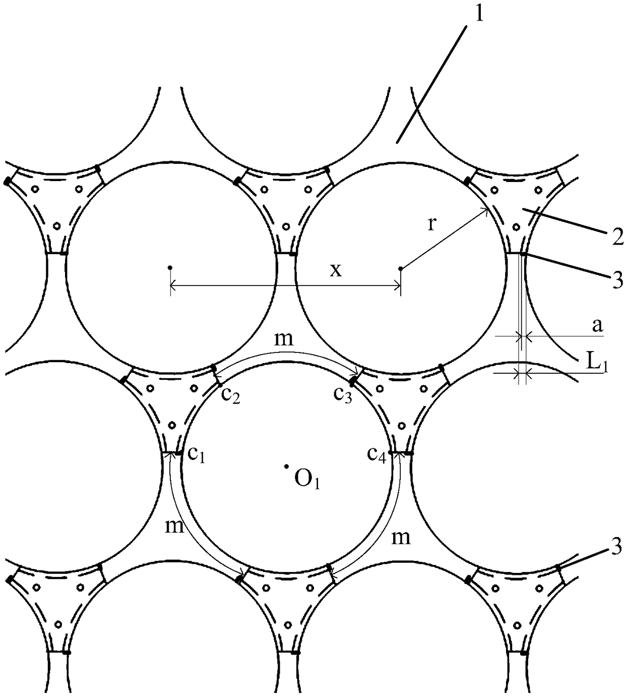
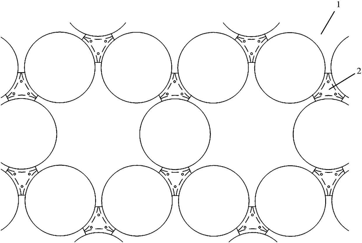
[0052] Such as figure 1 and combine Figure 2 to Figure 4 As shown, a lamp holder frame provided by an embodiment of the present invention includes a frame body 1, at least one pressing plate 2, and at least one baffle plate 3;
[0053] The pressing plate 2 is fixed on the frame body 1, so that the same three slide grooves are formed between the pressing plate 2 and the frame body 1;
[0054] There is at least one circular lamp holder installation position on the frame body 1, and at least two slide grooves exist at each lamp holder installation position;
[0055] Each of the chutes has a slide-in notch and a limit notch, and each of the limit notches is fixed with a baffle plate 3;
[0056] The width of the baffle 3 satisfies formula one;
[0057] The formula one includes: a≤(x-2r) / 2
[0058] Wherein, a is the width of the baffle 3, x is the length of the center line between any two adjacent lamp holder installation positions, and r is the radius of the lamp holder instal...
Embodiment 2
[0076] The second embodiment is basically the same as the first embodiment, and the similarities will not be repeated. The difference is that: for any of the lamp holder installation positions, there are three slide slots at the lamp holder installation position, and the three The chute is distributed at equal intervals along the center of the lamp holder installation position.
[0077] For example, if figure 1 As shown, there are 3 slide grooves at the installation position of the lamp holder, and for the 3 pressure plates required to form the 3 slide grooves, the connecting line between the centers of each pressure plate can be an equilateral triangle.
[0078] Correspondingly, as figure 1 As shown, point O for the center of the circle 1 There are three chutes at the lamp holder installation position, and the three chutes are along the center of the lamp holder installation position, that is, point O 1 , equally spaced distribution, the spacing values are figure 1 The ...
Embodiment 3
[0082] The third embodiment is basically the same as the second embodiment, and the similarities will not be described again. The difference is that: for the three chutes existing at any one of the lamp holder installation positions: including the adjacent first chute and the second chute;
[0083] The arc length between the slide-in notch of the first chute and the limit notch of the second chute and the sliding in between the limit notch of the first chute and the second chute The arc length between the notches is not less than the arc length of the first chute.
[0084] by figure 1 The center of the circle shown in is point O 1 Take the installation position of the lamp holder as an example, when the lamp holder is screwed into the installation position of the lamp holder, it is first necessary to place a clip of the lamp holder at point 2 and point c 3 between, and then rotate counterclockwise, thereby screwing the bar into point c 1 and point c 2 between.
[0085] ...
PUM
 Abstract
Description
Claims
Application Information
 - R&D Engineer
- R&D Manager
- IP Professional
- Industry Leading Data Capabilities
- Powerful AI technology
- Patent DNA Extraction
Browse by: Latest US Patents, China's latest patents, Technical Efficacy Thesaurus, Application Domain, Technology Topic, Popular Technical Reports.
© 2024 PatSnap. All rights reserved.Legal|Privacy policy|Modern Slavery Act Transparency Statement|Sitemap|About US| Contact US: help@patsnap.com


