
Smoke exhaust ventilator air valve mechanism, control method and device for smoke exhaust ventilator-gas stove linkage system and smoke exhaust ventilator-gas stove linkage system

A technology of smoke stove linkage and hood, applied in the field of hood damper mechanism, device, hood linkage system, and control method of hood linkage system, which can solve the problems of splitting wind pressure and hood damper unable to effectively exhaust smoke, etc. , to achieve the effect of improving the smoke exhaust efficiency

Active Publication Date: 2018-08-14
HANGZHOU ROBAM APPLIANCES CO LTD
View PDF8 Cites 0 Cited by
  • Summary
  • Abstract
  • Description
  • Claims
  • Application Information

AI Technical Summary

Problems solved by technology

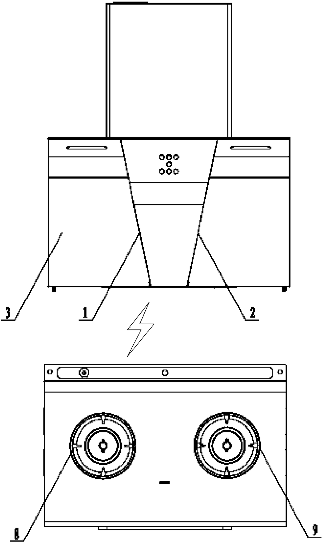
[0004] In view of this, the object of the present invention is to provide a hood damper mechanism, a control method and device for the hood linkage system, and the hood linkage system, so as to relieve the smoke caused by the non-working burner in the prior art. The damper of the machine will divide the wind pressure, resulting in the technical problem that the damper of the smoke machine corresponding to the working Reuters cannot exhaust smoke effectively

Method used


Image

  • Smoke exhaust ventilator air valve mechanism, control method and device for smoke exhaust ventilator-gas stove linkage system and smoke exhaust ventilator-gas stove linkage system
  • Smoke exhaust ventilator air valve mechanism, control method and device for smoke exhaust ventilator-gas stove linkage system and smoke exhaust ventilator-gas stove linkage system
  • Smoke exhaust ventilator air valve mechanism, control method and device for smoke exhaust ventilator-gas stove linkage system and smoke exhaust ventilator-gas stove linkage system

Examples


Embodiment Construction

[0043] In order to make the purpose, technical solutions and advantages of the embodiments of the present invention clearer, the technical solutions of the present invention will be clearly and completely described below in conjunction with the accompanying drawings. Obviously, the described embodiments are part of the embodiments of the present invention, not all of them. the embodiment. Based on the embodiments of the present invention, all other embodiments obtained by persons of ordinary skill in the art without making creative efforts belong to the protection scope of the present invention.

[0044] At present, when only one burner head of the gas stove is working, all the dampers of the hood are still opened at the same time. Since the maximum value of the air inlet air pressure generated by the hood used for exhausting smoke and draining steam is a fixed value, the burner that is not working The corresponding damper will divide part of the wind pressure, which will caus...


PUM


Abstract

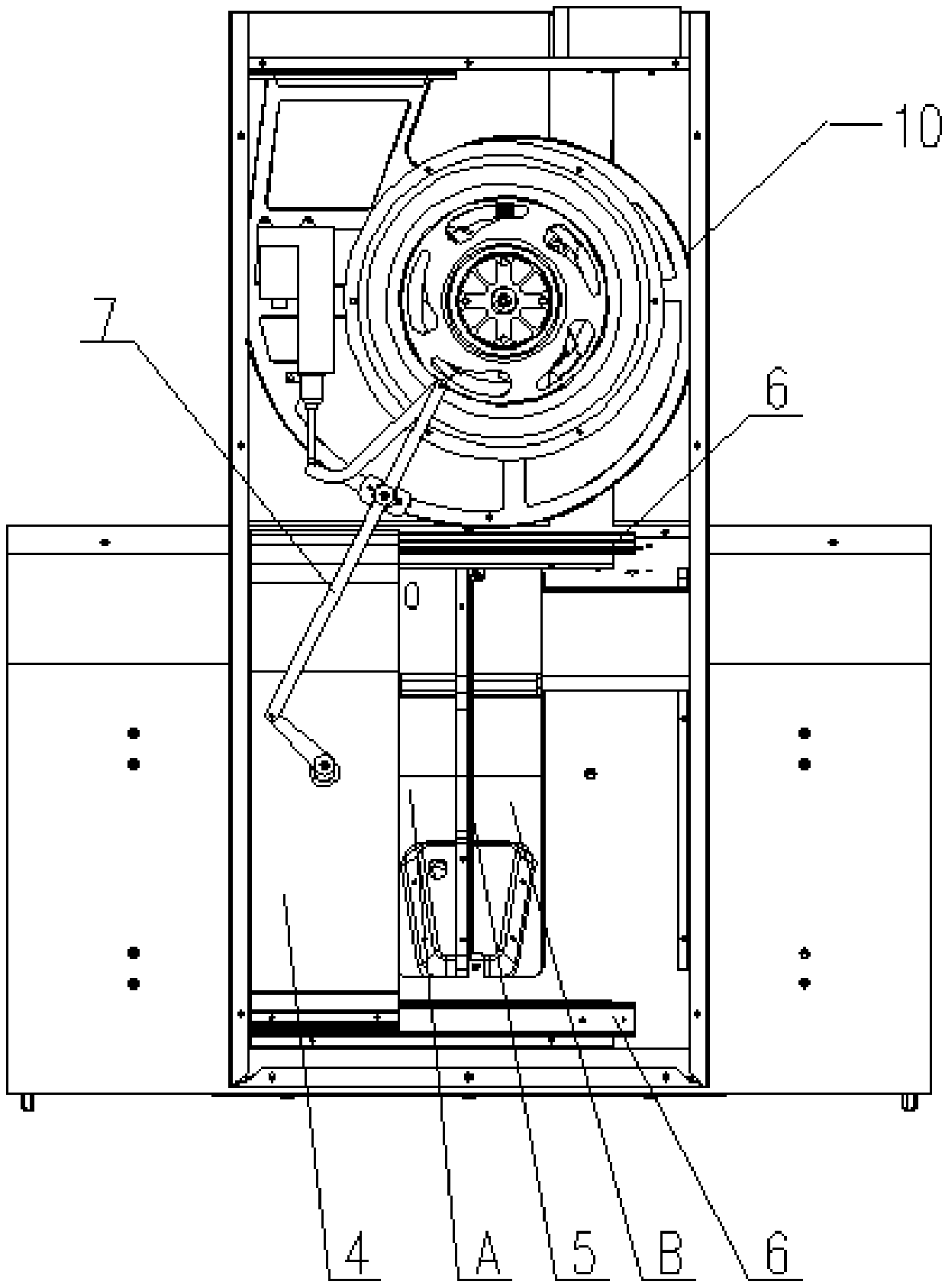
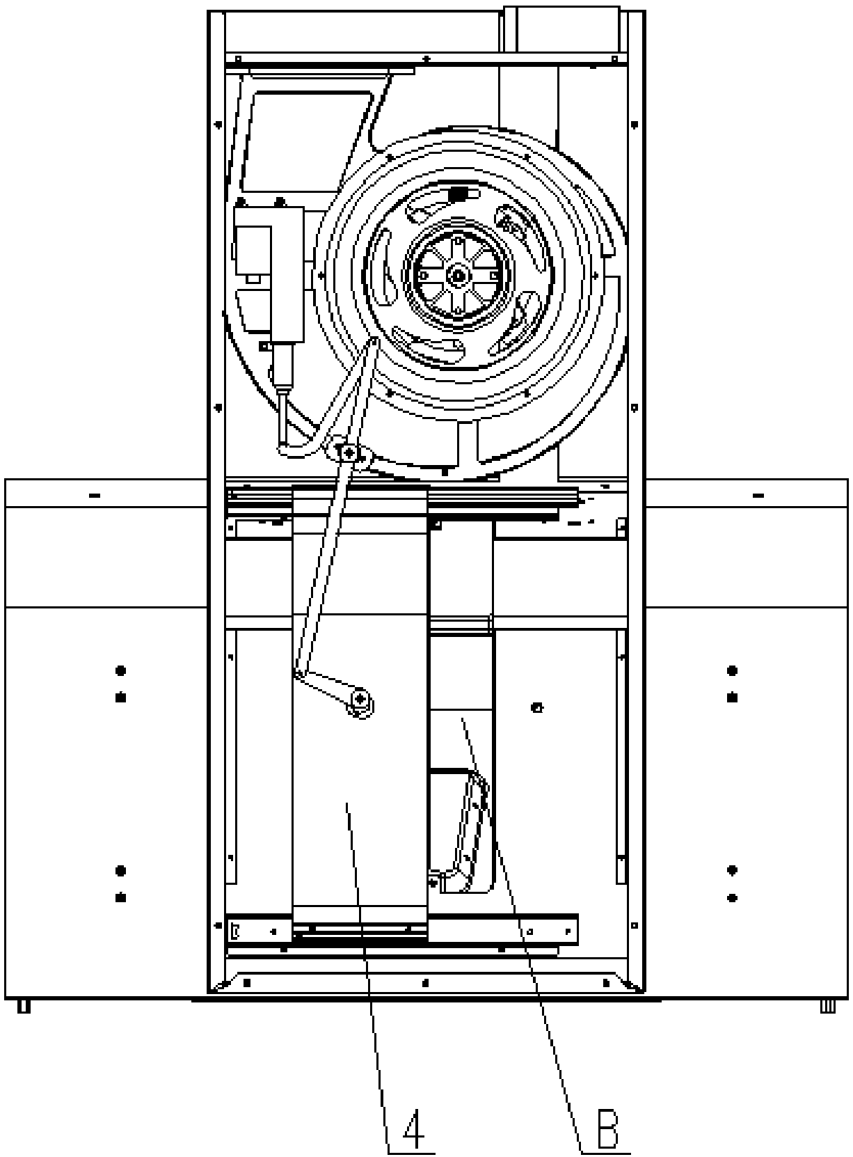
The invention provides a smoke exhaust ventilator air valve mechanism, a control method and device for a smoke exhaust ventilator-gas stove linkage system and the smoke exhaust ventilator-gas stove linkage system. The smoke exhaust ventilator air valve mechanism comprises a draught fan, an intermediate partition plate, a baffle, a baffle driving assembly and a slide rail assembly; the intermediatepartition plate is arranged at the center of an air inlet of the draught fan and partitions the air inlet into a left air inlet valve and a right air inlet valve which correspond to burners; the slide rail assembly is arranged on the edge of the air inlet and is perpendicular to the intermediate partition plate; and a group of opposite edges of the baffle are slidably connected with the slide rail assembly separately, and the preset position of the baffle is fixedly connected with the driving end of the baffle driving assembly. The baffle slides along the slide rail assembly under driving ofthe baffle driving assembly to adjust the air valve opening states of the left air inlet valve and / or the right air inlet valve, and the technical effects that all air pressure is concentrated on theair valve corresponding to the working burner, the condition that the air valve corresponding to the non-working burner takes away the air pressure is avoided, and the smoke exhaust efficiency is improved are achieved.

Description

technical field [0001] The invention relates to the technical field of kitchen appliances, in particular to a control method and device for a damper mechanism of a range hood, a range linkage system and a range range linkage system. Background technique [0002] Smoke stove linkage, as the name suggests, is to automatically turn on the integrated stove hood when using the gas stove, and automatically turn off the integrated stove after a certain period of time when the gas stove is stopped. The range hood linkage can avoid the situation of forgetting to turn on the range hood only when the range hood is overflowing. [0003] However, in practical application, the inventor found that when only one burner is working, all dampers of the hood are still opened at the same time. Since the maximum value of the wind pressure at the air inlet generated by the hood for exhausting smoke and draining steam is a fixed value, The damper corresponding to the non-working burner head will d...

Claims


Application Information

Patent Timeline
Patent Type & Authority Applications(China)
IPC IPC(8): F24C15/20F24C3/00
CPCF24C3/126F24C15/2021
Inventor 任富佳管兴勇
Owner HANGZHOU ROBAM APPLIANCES CO LTD
Learn More