Piezoelectric vibration energy collection device

An energy harvesting, piezoelectric vibration technology, applied in generators/motors, piezoelectric effect/electrostrictive or magnetostrictive motors, electrical components, etc. problem, to achieve the effect of efficient environmental vibration energy harvesting and overcoming application limitations

Pending Publication Date: 2018-08-14
ZHEJIANG GONGSHANG UNIVERSITY
View PDF2 Cites 7 Cited by
  • Summary
  • Abstract
  • Description
  • Claims
  • Application Information

AI Technical Summary

Problems solved by technology

The operating frequency of the linear single-frequency piezoelectric vibration energy harvester is relatively narrow, and the energy harvesting efficiency is low; the operating frequency band of the bistable piezoelectric vibration energy harvester is wide, and the efficiency of the energy harvester is high, but its output performance is affected by the intensity of environmental vibration Large, when the environmental vibration intensity is large enough, the bistable vibration is excited to produce a large conversion output; when the environmental vibration intensity is small, the bistable piezoelectric vibration energy harvester acts as a small-amplitude monostable vibration in the trap, This greatly reduces the output of the bistable piezoelectric vibration energy harvester
In addition, the currently developed bistable and tristable piezoelectric vibration energy harvesters are mainly magnet-

Method used


Image

  • Piezoelectric vibration energy collection device
  • Piezoelectric vibration energy collection device
  • Piezoelectric vibration energy collection device

Examples


Embodiment Construction

[0026] The technical solutions in the embodiments of the present invention will be clearly and completely described below in conjunction with the accompanying drawings in the embodiments of the present invention. Obviously, the described embodiments are only a part of the embodiments of the present invention, rather than all the embodiments. Based on the embodiments of the present invention, all other embodiments obtained by those of ordinary skill in the art without creative work shall fall within the protection scope of the present invention.

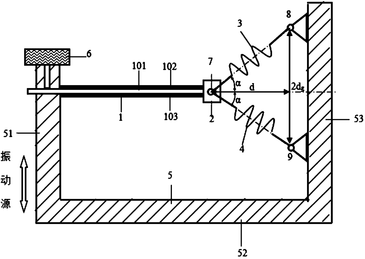
[0027] The purpose of the present invention is to provide a piezoelectric vibration energy harvesting device. Under the condition of low environmental excitation intensity and not being affected by strong magnetic fields, the piezoelectric vibration energy harvesting device can also easily perform large-scale periodic vibrations to achieve broadband, Efficient environmental vibration energy harvesting.

[0028] In order to make the above-m...


PUM


Abstract

The invention discloses a piezoelectric vibration energy collection device. The piezoelectric vibration energy collection device comprises a cantilever bimorph vibrator, a quality block, a first linear spring, a second linear spring, a base, a first hinge, a second hinge and a third hinge, one end of the cantilever bimorph vibrator is fixedly connected with a first support plate of the base, the other end of the cantilever bimorph vibrator is bonded with the quality block, the first hinge is arranged in the center of the quality block, the first hinge is connected with one end of the first linear spring and one end of the second linear spring separately, the second hinge and the third hinge are separately arranged on a second support plate of the base, the second hinge and the third hingeare respectively connected with the other end of the first linear spring and the other end of the second linear spring, the first hinge, the second hinge and the third hinge are in the same vertical plane and form an isosceles triangle, and the second hinge and the third hinge are symmetrically distributed on the second support plate with the cantilever bimorph vibrator as the center. The piezoelectric vibration energy collection device can perform periodic vibration drastically and easily even under conditions of low environment excitation strength and no strong magnetic field impact, and cancollect environment vibration energy under broadband efficiently.

Description

Technical field [0001] The invention relates to the field of power generation technology, and in particular to a piezoelectric vibration energy harvesting device. Background technique [0002] Piezoelectric vibration energy harvester is a new type of electromechanical energy conversion device that collects and converts mechanical vibration energy in the environment into electrical energy, and can be used to power low-power electronic products. The steady-state piezoelectric vibration energy harvesters currently developed mainly include linear single-frequency piezoelectric vibration energy harvesters and bistable piezoelectric vibration energy harvesters. The working frequency of linear single frequency piezoelectric vibration energy harvester is relatively narrow, and the energy harvesting efficiency is low; the working frequency bandwidth of bistable piezoelectric vibration energy harvester, the energy harvester has high efficiency, but its output performance is affected by the...

Claims


Application Information

Patent Timeline
IPC IPC(8): H02N2/18
CPCH02N2/186
Inventor 王光庆王学保李秀玲
Owner ZHEJIANG GONGSHANG UNIVERSITY
Why Eureka
Try Eureka