
Planar orthomode transducer

a transducer and orthomode technology, applied in the field of microwave devices, can solve the problems of large dimensions, high manufacturing cost, and difficulty in integrating such waveguide orthomode transducers into the microwave front-end of the transceiver device, and achieve the effects of improving polarization diversity, widening the operating frequency band, and reducing insertion losses

Active Publication Date: 2019-06-20
INFINET LLC
View PDF2 Cites 1 Cited by
  • Summary
  • Abstract
  • Description
  • Claims
  • Application Information

AI Technical Summary

Benefits of technology

The patent describes a way to improve the performance of a planar orthomode transducer by using a substrate integrated resonator and waveguides. The resonator helps widen the operating frequency band, reduces insertion losses, and improves polarization diversity. The substrate integrated waveguides connect to the resonator and antennas of various types. The absence of resonating elements in the resonator reduces insertion loss and improves impedance matching. Different shapes of the planar orthomode transducer make it versatile and compatible with different antennas. Overall, this solution makes it easier to design and connect the transducer to various types of antennas.

Problems solved by technology

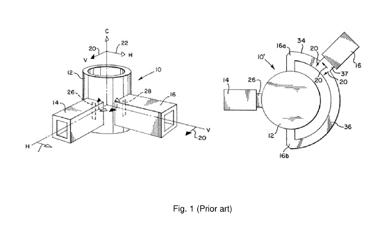
The main drawbacks of such orthomode transducer are large dimensions, complexity and, consequently, high manufacturing cost since the high-precision milling or welding of several complex metal pieces is required.
It leads to the fact that it is hard to integrate such waveguide orthomode transducer into the microwave front-end of the transceiver devices.
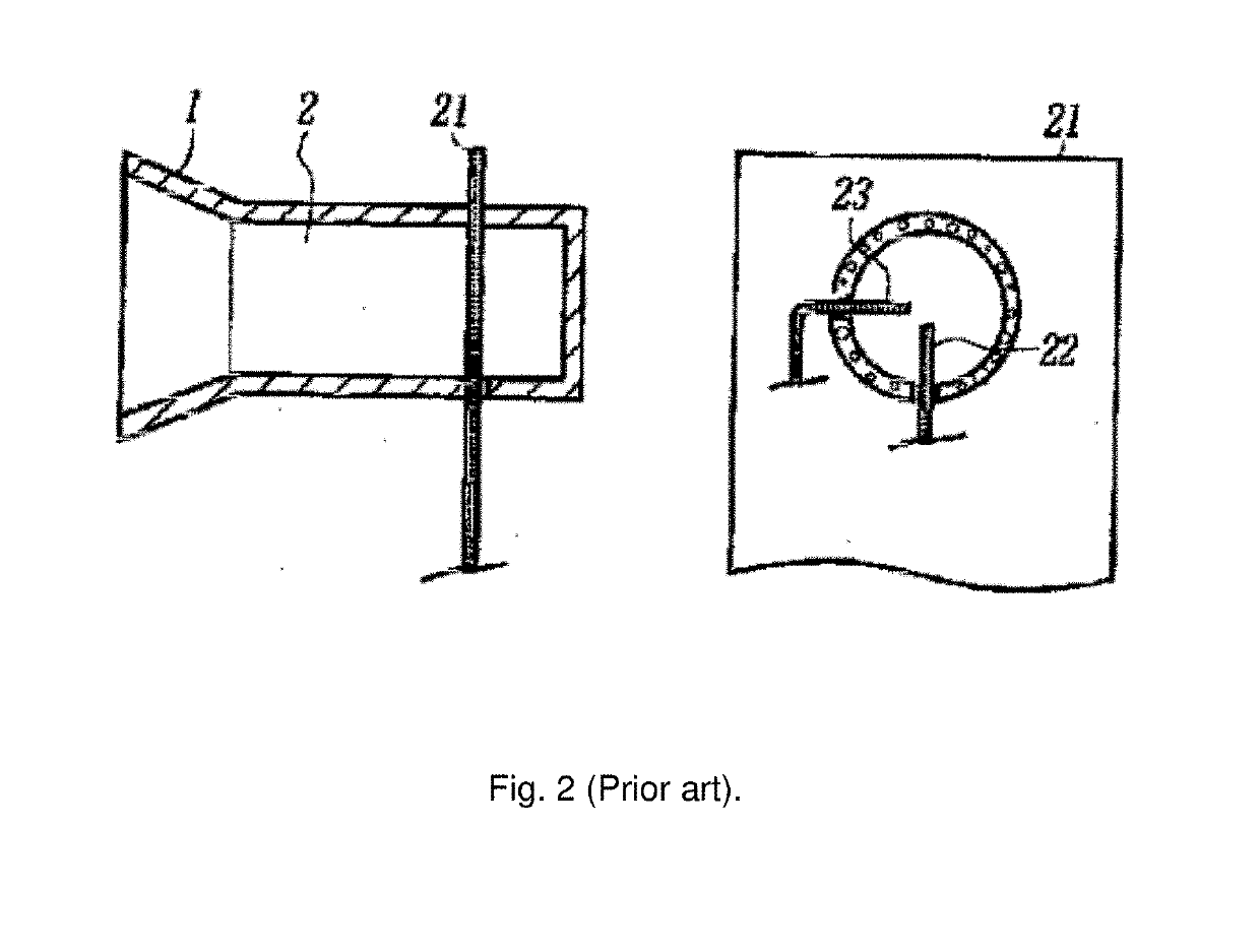
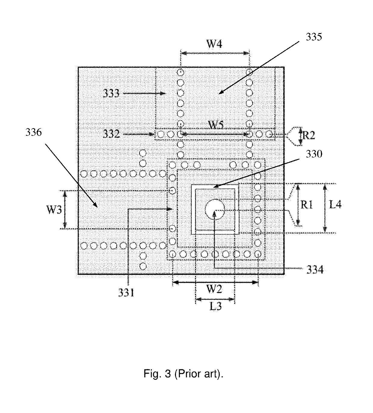
However, the probe based orthomode transducer implemented on the printed circuit board has several other drawbacks.
1. Lack of versatility. The usage of the primary antenna element together with the main antenna significantly decreases the variety of possible antenna designs which can be implemented together with the primary antenna element. In other words, the considered orthomode transducer does not have a commonly used dual polarized port such as, for example, a dual polarized metal waveguide. This prevents from using different antennas with the orthomode transducer and significantly limits its applications. Such approach cannot be implemented for very common horn antennas or integrated lens antennas which have waveguide feed radiator placed on the flat lens surface;
2. Narrow frequency band. As such, a resonant cavity slot antenna is a narrow conductive frame which starts to radiate at the tuning frequency that depends on the frame perimeter. That is why both the antenna and, consequently, the orthomode transducer have relatively narrow operational frequency range (4%) that has been confirmed by experimental data as presented in CN104752841;
3. Low isolation between orthogonal polarizations. An experimental orthogonal polarization isolation of the described orthomode transducer is only 22 . . . 23 dB in the operational frequency band (data also shown in CN104752841). For many wireless communication applications this isolation could be not enough;
4. High insertion loss. The considered orthomode transducer with the primary antenna element has relatively high insertion loss due to the narrow radiating slot of the resonant cavity loop frame. A narrow slot in the loop frame increases the surface current density and the electric field intensity in dielectric near to the slot. This increases the insertion loss level.

Method used


Image

  • Planar orthomode transducer
  • Planar orthomode transducer
  • Planar orthomode transducer

Examples


Embodiment Construction

[0046]One embodiment of the present invention of a planar orthomode transducer is shown in FIG. 4. It comprises a substrate integrated resonator (1) with two substrate integrated waveguides (2) connected to the substrate integrated resonator (1), wherein the substrate integrated resonator (1) and the substrate integrated waveguides (2) are formed by a plurality of metallized via holes between two metallization layers of a printed circuit board (10). The substrate integrated waveguide (2) is shown in FIG. 5. Metallized via holes connecting bottom and top metallization layers of the printed circuit board (10) form sidewalls of the substrate integrated waveguides (2). Top and bottom metallization layers of the printed circuit board (10) form top and bottom walls of the substrate integrated waveguides (2). Thus, substrate integrated waveguides (2) have dielectric filling that consists of the printed circuit board (10) substrate material. Operating principle of the substrate integrated w...


PUM


Abstract

A planar orthomode transducer comprises a substrate integrated resonator, two substrate integrated waveguides connected to the substrate integrated resonator, a dual polarized metal waveguide and a printed circuit board where the substrate integrated resonator and the substrate integrated waveguides are provided, wherein the substrate integrated resonator further comprises a slot aperture in one of metallization layers, and the dual polarized metal waveguide is mounted on a surface of the printed circuit board in an area of the slot aperture of the substrate integrated resonator, wherein the substrate integrated resonator is a nonfundamental orthogonal mode resonator.This enables widening of frequency band of the planar orthomode transducer, reducing of insertion losses, rise of the polarization diversity and providing for a standard dual polarized output waveguide serving for connecting the device with an antenna of various types.

Description

FIELD OF THE INVENTION[0001]The present invention relates to the field of microwave devices and more specifically to splitters or combiners of electromagnetic waves with orthogonal polarizations.BACKGROUND OF THE INVENTION[0002]One of the methods to increase a wireless communication system throughput is the usage of two orthogonal polarizations than can be done without significant sophistication of the transceiver. This enables a simultaneous transmission and / or receipt of two data flows, each flow being carried by orthogonally polarized electromagnetic waves. The key components of such a system are dual polarized antennas and orthomode transducers, which are devices used to distinguish appropriately polarized waves from the common dual-pol antenna port. Each of single-pol waves is guided to one or more orthomode transducers ports.[0003]Traditionally, orthomode transducers are provided on hollow metallic waveguides, and more specifically on several waveguides of rectangular cross-se...

Claims


Application Information

Patent Timeline
Patent Type & Authority Applications(United States)
IPC IPC(8): H01P1/161H01P1/213
CPCH01P1/161H01P1/213H01P5/024
Inventor CHURKIN, SERGEY SERGEEVICHARTEMENKO, ALEKSEY ANDREEVICHMOZHAROVSKIY, ANDREY VIKTOROVICHMASLENNIKOV, ROMAN OLEGOVICH
Owner INFINET LLC
Learn More