Microwave power splitter based on left-right-hand composite transmission line

A technology of left-handed composite and microwave power splitter, which is applied in the direction of waveguide devices, electrical components, circuits, etc., can solve the problems of high manufacturing process requirements, narrow working frequency band, and complex structure, and achieve small size, good performance, and simple structure Effect

Inactive Publication Date: 2008-07-09
ZHEJIANG UNIV
View PDF4 Cites 1 Cited by
  • Summary
  • Abstract
  • Description
  • Claims
  • Application Information

AI Technical Summary

Problems solved by technology

[0005] The purpose of the present invention is to integrate microwave and millimeter wave circuits more compactly and efficiently, overcome the shortcomings of existing microwave power splitters such as narrow operating frequency band, low frequency, complex structure, large size, and high manufacturing process requirements, and provide a A microwave power splitter based on left-handed composite transmission lines with large narrow operating frequency band, low insertion loss, power equalization, low cost, small size, and easy fabrication and integration

Method used


Image

  • Microwave power splitter based on left-right-hand composite transmission line
  • Microwave power splitter based on left-right-hand composite transmission line
  • Microwave power splitter based on left-right-hand composite transmission line

Examples


Embodiment Construction

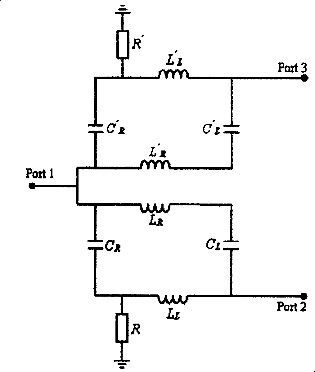
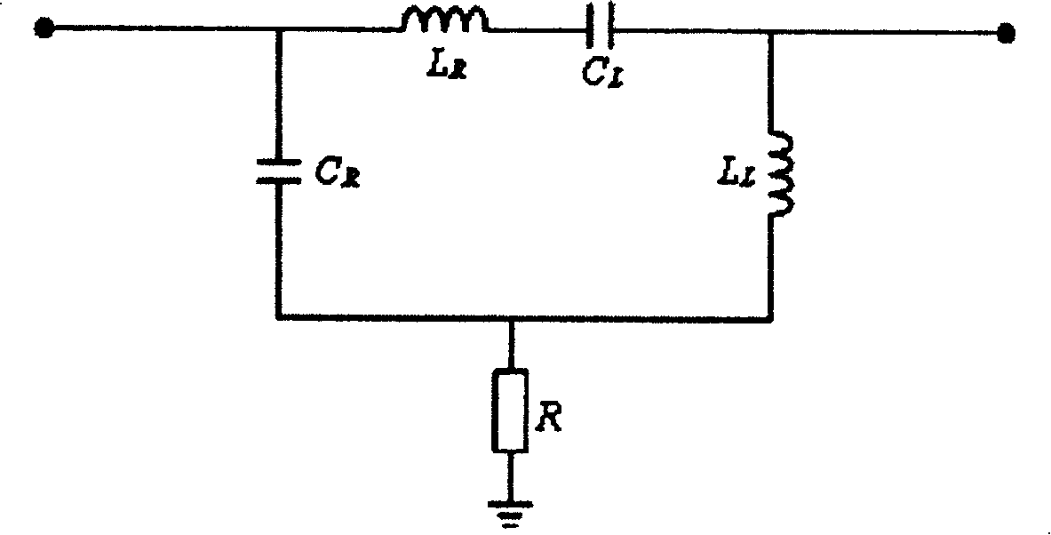
[0013] A plurality of left-hand composite transmission line units are connected in parallel, and the left-hand composite transmission line unit is: right-hand material inductance L R , left-hand material capacitance G L After being connected in series, the inductance L of the left-hand material connected in series with each other L and the right-hand material capacitance C R Connect in parallel; at the same time, one end of the resistor R is connected to the left-hand material inductance L L and the right-hand material capacitance C R middle, while the other end is grounded. The signal is input by port 1 and output by port 2 and port 3. By choosing to increase or decrease (2-3) the number of right-handed composite transmission line units connected in parallel to obtain the required performance index of the microwave power splitter.

[0014] An example of a microwave power splitter based on a left-handed composite transmission line: according to the required power division...


PUM


Abstract

The invention discloses a microwave power divider that bases on left-right hand combination transmission lines, which has a plurality of parallel left-right hand combination transmission units that include: right-hand material inductor LR connected with left-hand material capacitor CL in series, and parallel arranged with left-hand material inductor LL and right-hand material capacitor CR, and then connected with resistance R in series. The inventive microwave power divider has the advantages of be able to obtain high working frequency band, low insertion loss and equal power.

Description

technical field [0001] The invention relates to a microwave power divider based on left and right hand composite transmission lines. Background technique [0002] Microwave power divider is a multi-port microwave network that divides the input signal power into equal or unequal power outputs, and is widely used in radio frequency or microwave communication, satellite communication, wireless communication, cable TV, microwave phase array antenna . [0003] At present, the known practical microwave power splitters are usually divided into Wilkinson structure, T-shaped structure, disk-shaped or fan-shaped, wedge-shaped structure of Gupta et al., or power splitters composed of directional coupled microstrip lines. However, these existing microwave power splitters have the disadvantages of narrow operating frequency band, low frequency, complex structure, large size, and high manufacturing process requirements. [0004] Working frequency band, size, mass size, structural comple...

Claims


Application Information

Patent Timeline
Patent Type & Authority Patents(China)
IPC IPC(8): H01P1/387
Inventor 李九生邹勇卓何赛灵
Owner ZHEJIANG UNIV
Why Eureka
Try Eureka