
Air conditioner fan blade bearing seat assembly and air conditioner indoor unit

A technology for air-conditioning indoor units and bearing housings, which is applied to bearing elements, rigid supports of bearing components, air-conditioning systems, etc., and can solve problems such as fan blade bearing housings falling out, fan blade bearing housings not being installed in place, increased costs, and processing complexity, etc. problem, to avoid the effect of prolapse

Active Publication Date: 2018-08-17
AUX AIR CONDITIONING LTD BY SHARE LTD
View PDF10 Cites 0 Cited by
  • Summary
  • Abstract
  • Description
  • Claims
  • Application Information

AI Technical Summary

Problems solved by technology

[0002] Existing air-conditioning fan blade bearing seats are all conventional cylindrical structures. During assembly, the traditional fan blade bearing seat and bearing fixing seat are assembled from the fan blade end to the outside, and the assembly entrance of the bearing fixing seat faces the fan blade end. The bit structure is on the outside, and there is a risk that the fan blade bearing seat is not installed in place
At the same time, after the air conditioner has been running for a long time, the fan blade bearing seat may come out of the fan blade due to looseness or aging, both of which will cause interference with the side of the fan blade, affecting the normal rotation of the fan blade, thereby affecting the normal operation of the air conditioner
[0003] In the prior art, when assembling the air conditioner fan blade bearing seat, it is carried out from the fan blade end, and it is necessary to set a baffle on the outside of the bearing seat to limit the fan blade bearing to prevent the bearing from protruding from the outside of the bearing seat. The method greatly increases the cost and processing complexity

Method used


Image

  • Air conditioner fan blade bearing seat assembly and air conditioner indoor unit
  • Air conditioner fan blade bearing seat assembly and air conditioner indoor unit
  • Air conditioner fan blade bearing seat assembly and air conditioner indoor unit

Examples


Embodiment 1

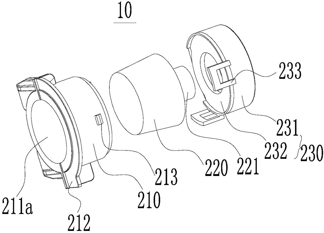
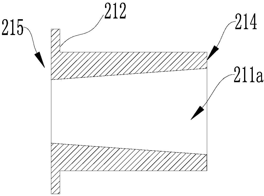
[0033] Such as figure 1 As shown, the present embodiment provides an air conditioner fan blade bearing seat assembly 10, which includes a bearing seat 210, a fan blade bearing 220 and a bearing fixing member 230, see figure 2 , figure 2 Shows the cross-sectional structural view of the bearing seat 210 in this embodiment, wherein the bearing seat 210 has an opposite first end 214 and a second end 215, the bearing seat 210 is provided with a mounting hole 211a for installing the fan blade bearing 220, and the mounting hole 211a penetrates through the bearing seat 210 along the direction from the first end 214 to the second end 215 . The axis of the installation hole 211 a coincides with the axis of the bearing housing 210 , wherein the installation hole 211 a is used for installing or assembling the blade bearing 220 .

[0034] At least a part of the installation hole 211a is a variable diameter section, where the variable diameter section refers to the extension direction o...

Embodiment 2

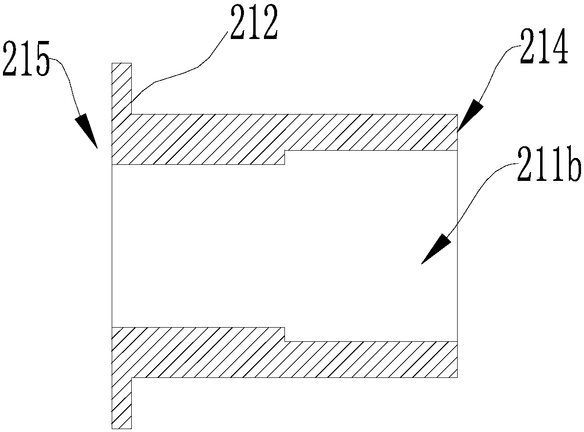
[0046] Such as image 3 As shown, this embodiment provides an air conditioner fan bearing seat assembly 10, which is different from the air conditioner fan bearing seat assembly 10 provided in Embodiment 1 in that the bearing seat 210 is provided with a mounting hole 211b, wherein the mounting hole 211b The structural arrangement of the reducing section is different from that of the mounting hole 211a in Embodiment 1. Correspondingly, the structure of the blade bearing 220 matched with the mounting hole 211b is matched with the structure of the bearing housing 210 in this embodiment.

[0047] Specifically, see image 3 , in this embodiment, the mounting hole 211a on the bearing seat 210 has a diameter reducing section, which is located in the middle of the mounting hole 211a, and the diameter reducing section only includes a part of the mounting hole 211b, and the diameter reducing section The inner diameter is a sudden design, that is, the installation hole 211b is a stepped...

Embodiment 3

[0052] refer to Figure 4 This embodiment provides an air conditioner indoor unit, including the fan blade 100, the base 110 and the air conditioner fan blade bearing seat assembly 10 of Embodiment 1, wherein the base 110 is a part of the air conditioner indoor unit for installation on a wall. In the air-conditioning indoor unit in this embodiment, the bearing seat 210 is installed on the base 110, and the small end of the variable diameter section of the installation hole 211a is set toward the side of the fan blade 100, and the large end of the variable diameter section of the installation hole 211a faces the base 110 Outer setting. The fan blade bearing 220 is installed in the installation hole 211a, and the fan blade 100 is installed on the fan blade bearing 220 .

[0053] Wherein the fan blade bearing 220 is matched with the installation hole 211 a of the bearing seat 210 .

[0054] read on Figure 5 with Image 6 , the second abutting portion 232 of the bearing fixin...


PUM


Abstract

The invention provides an air conditioner fan blade bearing seat assembly and an air conditioner indoor unit, and belongs to the technical field of household appliances. The air conditioner fan bladebearing seat assembly comprises a bearing seat, and a mounting hole used for mounting a fan blade bearing is formed in the bearing seat; at least one part of the mounting hole is a variable diameter section; the fan blade bearing can be mounted in the mounting hole; and a bearing fixing part is used for preventing the fan blade bearing from separating from a first end. According to the air conditioner indoor unit provided with the air conditioner fan blade bearing seat assembly, during assembly, the small opening end of the variable diameter section of the bearing seat faces a fan blade, the fan blade bearing is assembled into the mounting hole from the outer side of the fan blade, the variable diameter section is arranged, and the fan blade bearing is limited by the variable diameter section, so that the fan blade bearing is prevented from separating from one end of the fan blade to interfere operation of the fan blade.

Description

technical field [0001] The invention relates to the technical field of home appliances, in particular to an air conditioner fan blade bearing seat assembly and an air conditioner indoor unit. Background technique [0002] Existing air-conditioning fan blade bearing seats are conventional cylindrical structures. During assembly, the traditional fan blade bearing seat and bearing fixing seat are assembled from the fan blade end to the outside, and the assembly entrance of the bearing fixing seat faces the fan blade end. The bit structure is on the outside, and there is a risk that the fan blade bearing seat may not be installed in place. At the same time, after the air conditioner has been running for a long time, the fan blade bearing seat may come out of the fan blade due to looseness or aging, both of which will cause interference with the side of the fan blade, affecting the normal rotation of the fan blade, thereby affecting the normal operation of the air conditioner . ...

Claims


Application Information

Patent Timeline
Patent Type & Authority Applications(China)
IPC IPC(8): F24F1/00F16C35/00
CPCF16C35/00F24F1/0018Y02B30/70
Inventor 尚彬周杨曾友坚
Owner AUX AIR CONDITIONING LTD BY SHARE LTD
Learn More