
Vibration tests and methods for simulating adhesive motion on elastic planes in microgravity
A technology that simulates microgravity and vibration testing. It is applied in vibration testing, machine/structural component testing, and measuring devices. It can solve problems such as vibration testing and its control methods that have not yet been reported, improve experimental testing performance, and facilitate the realization of motion. , the effect of simple structure
- Summary
- Abstract
- Description
- Claims
- Application Information
AI Technical Summary
Problems solved by technology
Method used
Image

Examples
Embodiment Construction
[0020] Below in conjunction with accompanying drawing and specific embodiment the present invention is described in further detail:
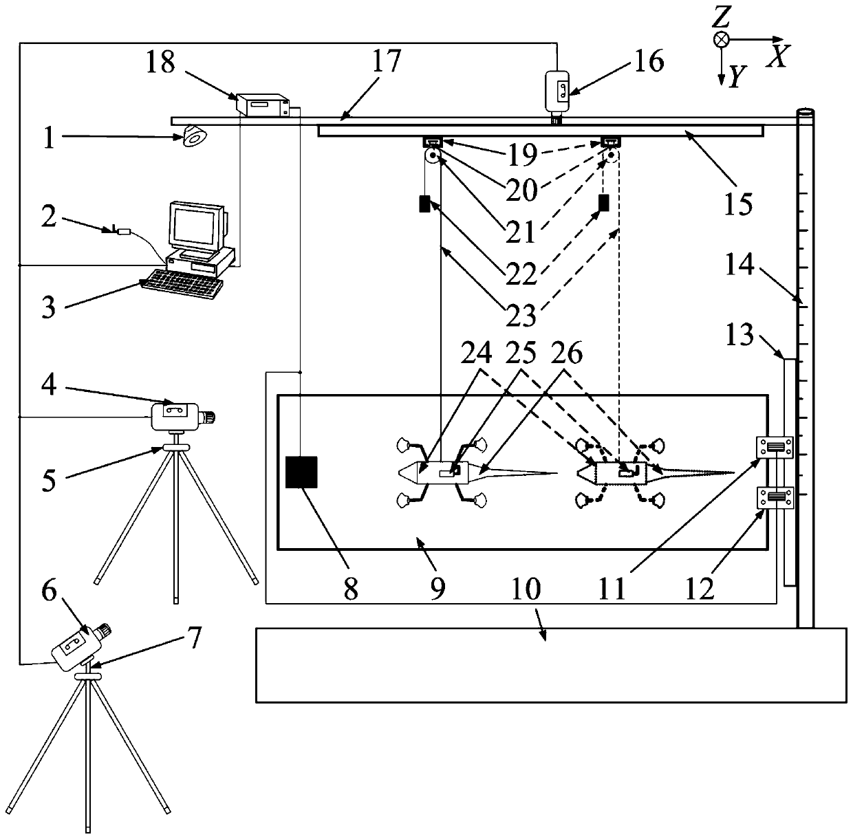
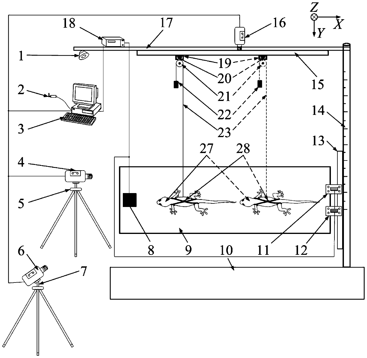
[0021] combine figure 1, this embodiment is a vibration test and control method for simulating the adhesion motion on an elastic plane under microgravity, including a light source 1, a host computer wireless communication module 2, a computer control terminal 3, an X-direction high-speed camera 4, and an X-direction tripod 5 , Z-direction high-speed camera 6, Z-direction tripod 7, micro-inertial navigation module 8, elastic plate 9, platform base 10, Y-axis No. A torque sensor 11, Y-axis No. B torque sensor 12, connecting plate 13, support Scale rod 14, X-direction moving slide rail groove 15, Y-direction high-speed camera 16, supporting top plate 17, sensor data acquisition system 18, Z-direction moving slide rail groove 19, Z-direction moving slide rail block 20, fixed pulley 21, distribution Heavy object 22, string 23, legged robot main body...
PUM
 Abstract
Description
Claims
Application Information