
Sequential batch test piece introduction device for two-box thermal shock experiment box

A leading-in device and thermal shock technology, which is applied in the field of sequentially leading-in devices for batch test pieces, can solve problems such as poor reliability, difficulty in realizing a large-scale adjustment of speed, and inability to ensure the consistency of the test environment, etc., and achieve the effect of improving efficiency

Active Publication Date: 2018-08-17
CHONGQING UNIV
View PDF6 Cites 0 Cited by
  • Summary
  • Abstract
  • Description
  • Claims
  • Application Information

AI Technical Summary

Problems solved by technology

[0005] 1. Since only one specimen can be clamped in one experiment, the efficiency of the experiment is low
[0006] 2. Use spring clips to clamp the specimen. Only one specimen can be clamped in one experiment. Due to the intrinsic brittleness of the material, the results of the thermal shock test are highly dispersed, and only one specimen can be used in one experiment. The test environment needs to be reloaded during the experiment, and the consistency of the test environment cannot be guaranteed to eliminate the influence of the difference in the test environment, resulting in low accuracy and poor reliability of the characterization results
[0007] 3. Since the falling posture of the test piece in this patent is controlled by the collar and the guide wire, it is difficult to realize the large-scale adjustment and control of the speed
[0008] 4. Since the spring clip of the clamping device can only be used at a lower initial temperature, it cannot achieve thermal shock at a higher initial temperature
[0009] The above problems caused large errors in the test process, and the test results were not comprehensive and could not characterize the thermal shock resistance of ceramic materials well.

Method used


Image

  • Sequential batch test piece introduction device for two-box thermal shock experiment box
  • Sequential batch test piece introduction device for two-box thermal shock experiment box
  • Sequential batch test piece introduction device for two-box thermal shock experiment box

Examples


Embodiment Construction

[0022] The present invention will be further described below in conjunction with accompanying drawing:

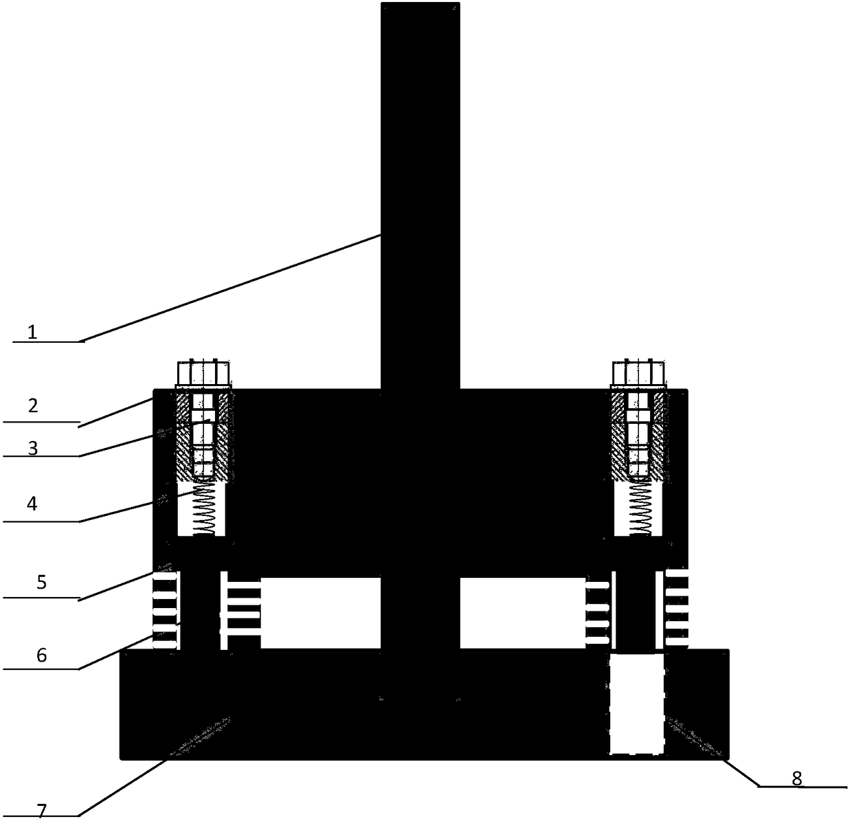
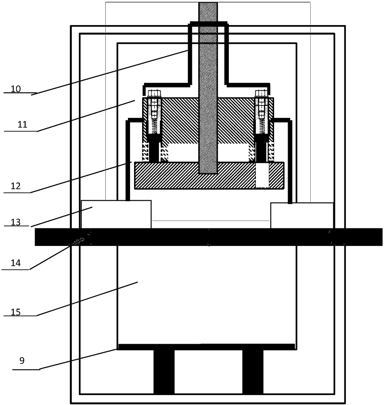
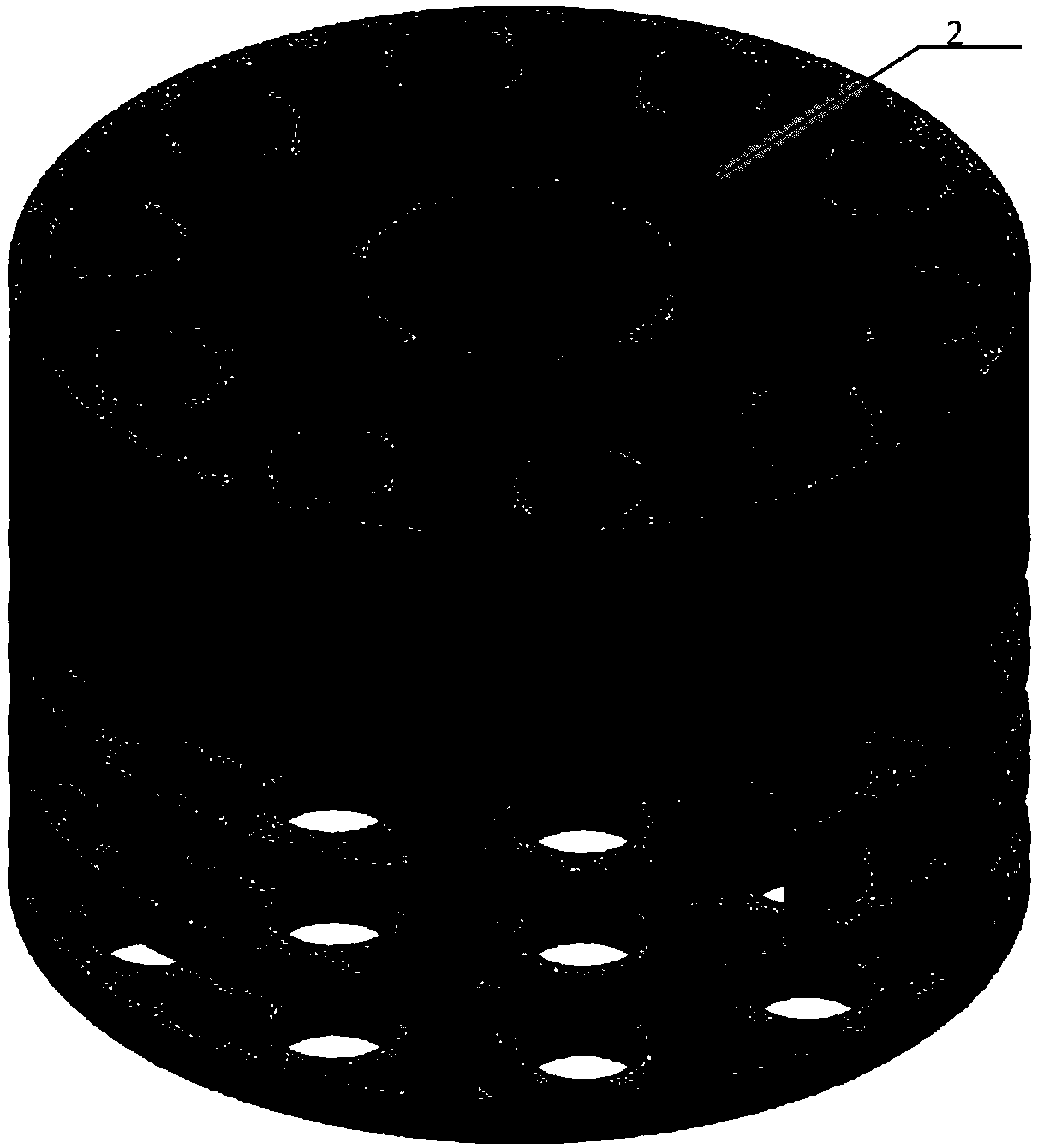
[0023] Such as figure 1 with figure 2 As shown, the present invention includes a rotating shaft 1 , a specimen holding disc 2 and a baffle plate 7 with holes. A graphite sleeve 10 is sheathed on the specimen holding disc 2, and a heat insulation zone is formed between the two. One end of the rotating shaft 1 penetrates through the specimen holding disc 2 and the graphite sleeve 10, and is embedded in the perforated baffle 7 to connect with it, and the other end extends out of the high temperature chamber and is rotatable. There are a group of holes evenly distributed in the circumferential direction on the specimen holding plate 2, and bolts 3, springs 4, heat insulation protection structures 5, and specimens 6 are installed in each hole in sequence from top to bottom, corresponding to the vertical height area of ​​the specimen. The test piece holding disc 2 is hollowed...


PUM


Abstract

The invention discloses a sequential batch test piece introduction device for a two-box thermal shock experiment box. The device comprises a rotating shaft, a test piece holding plate and a perforatedbaffle plate. A graphite sleeve sleeves the test piece holding plate, and a heat insulating area is formed between the graphite sleeve and the test piece holding plate. One end of the rotating shaftpenetrates through the test piece holding plate and the graphite sleeve, and is embedded in the perforated baffle plate, and the other end of the rotating shaft extends outside a high temperature chamber. The test piece clamping plate is provided with a batch of holes, a bolt, a spring, a heat insulating protection structure and a test piece are sequentially arranged in every hole from top to bottom, and the test piece holding plate corresponding to the vertical height areas of the test pieces is distantly hollowed-out. A through hole is arranged in the perforated baffle plate. The test pieceholding plate is fixed by a support. The device has the following advantages: the test pieces have a high initial temperature and are uniformly heated, and the target temperature of the thermal shockand the initial thermal shock environment are accurately controlled, so the test accuracy and the test efficiency are improved.

Description

technical field [0001] The invention relates to a temperature shock test device, in particular to a device for sequentially introducing batch test pieces into a two-box thermal shock test box. Background technique [0002] Ultra-high-temperature ceramics (UHTCs for short) generally refer to a class of ceramic materials used at high temperatures above 2000°C, mainly referring to borides, carbides and nitrides of some transition metals. [0003] Hypersonic vehicles are an important field for aerospace technology to explore new flight limits. It will greatly promote the realization of aerospace integration, and it is a hot field for the development of advanced aviation countries in recent years. With the increase in the mobility and penetration capabilities of aerospace vehicles, countries around the world have successively carried out research on hypersonic vehicles in recent years. The ultra-high temperature ceramic material has a high melting point of about 3000 ° C, as we...

Claims


Application Information

Patent Timeline
IPC IPC(8): G01N3/60G01N3/02
CPCG01N3/02G01N3/60G01N2203/0226
Inventor 李卫国冯开翔彭方澜王文玲麻建坐陶勇寇海波邵家兴张先贺邓勇李莹张续耀张欣徐念东董攀方岱宁
Owner CHONGQING UNIV
Learn More