Dust collection device
A dust removal device and dust storage technology, which is applied in the direction of combined devices, dispersed particle separation, chemical instruments and methods, etc., can solve the problems of inconvenient cleaning and easy flying of dust, etc.
- Summary
- Abstract
- Description
- Claims
- Application Information
AI Technical Summary
Problems solved by technology
Method used
Image

Examples
Embodiment Construction
[0023] Specific embodiments of the present invention will be described in detail below in conjunction with the accompanying drawings. It should be understood that the specific embodiments described here are only used to illustrate and explain the present invention, and are not intended to limit the present invention.
[0024] In the present invention, in the absence of a contrary statement, orientation words such as "inner, outer, bottom, upper and lower" included in the term only represent the orientation of the term in a conventional use state, or are technically known in the art. A common term as understood by persons and should not be construed as a limitation of the term.
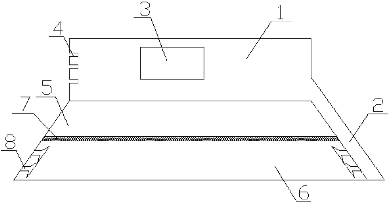
[0025] The invention provides a dust removal device, wherein, as figure 1 As shown, the dust removal device includes a fan placement chamber 1 and a dust storage chamber connected in sequence from top to bottom, and the fan placement chamber 1 is also communicated with a through pipe 2 arranged on the...
PUM
 Abstract
Description
Claims
Application Information