An oscillating conveyor belt for cooling fins

A technology for conveyor belts and heat sinks, applied in the field of conveyor belts, can solve the problems of falling damage to heat sinks, inconvenient stacking and collection of heat sinks, unfavorable heat sink processing operations, etc., to achieve low equipment costs and prevent bump damage

Active Publication Date: 2019-11-05
KUNSHA KEMO PRECISION MACHINE
View PDF10 Cites 0 Cited by
  • Summary
  • Abstract
  • Description
  • Claims
  • Application Information

AI Technical Summary

Problems solved by technology

[0002] At present, the outer contour of the main body of the heat sink processed by the continuous die is in the shape of a cuboid, and the cuboid heat sink is vertically blanked due to the shape, so that the position of the heat sink after blanking is disordered, and it is easy to cause drop damage to the heat sink. It is not convenient for subsequent stacking and collection of heat sinks, and it is also not conducive to subsequent processing of heat sinks

Method used


Image

  • An oscillating conveyor belt for cooling fins
  • An oscillating conveyor belt for cooling fins
  • An oscillating conveyor belt for cooling fins

Examples


Embodiment Construction

[0033] Below in conjunction with specific embodiment, content of the present invention is described in further detail:

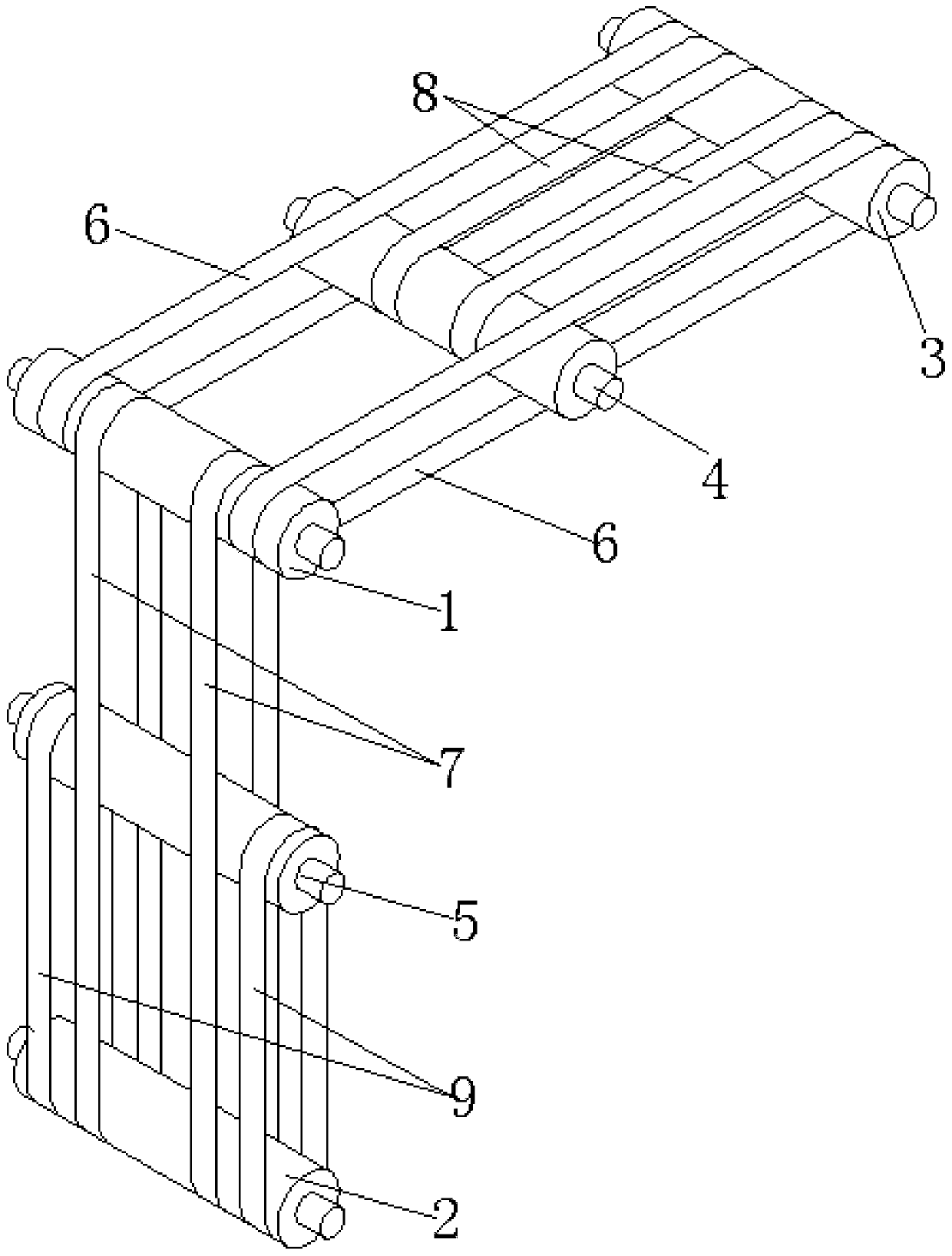
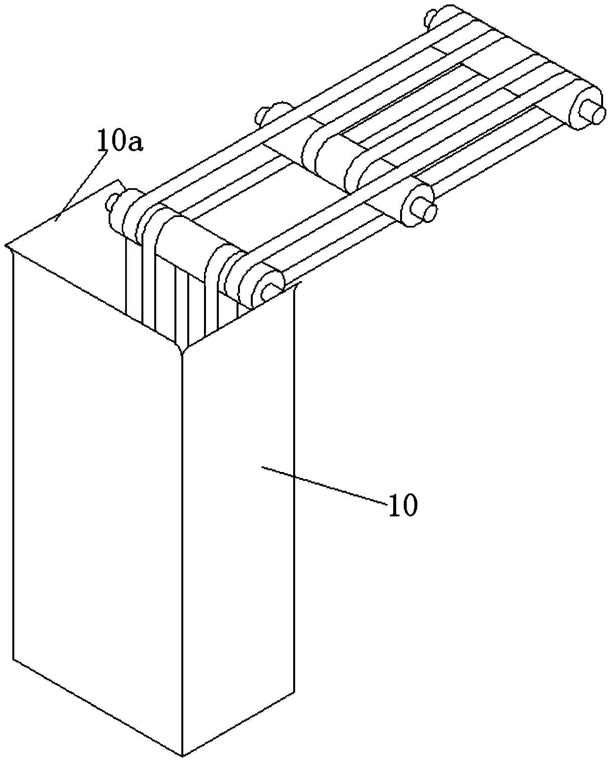
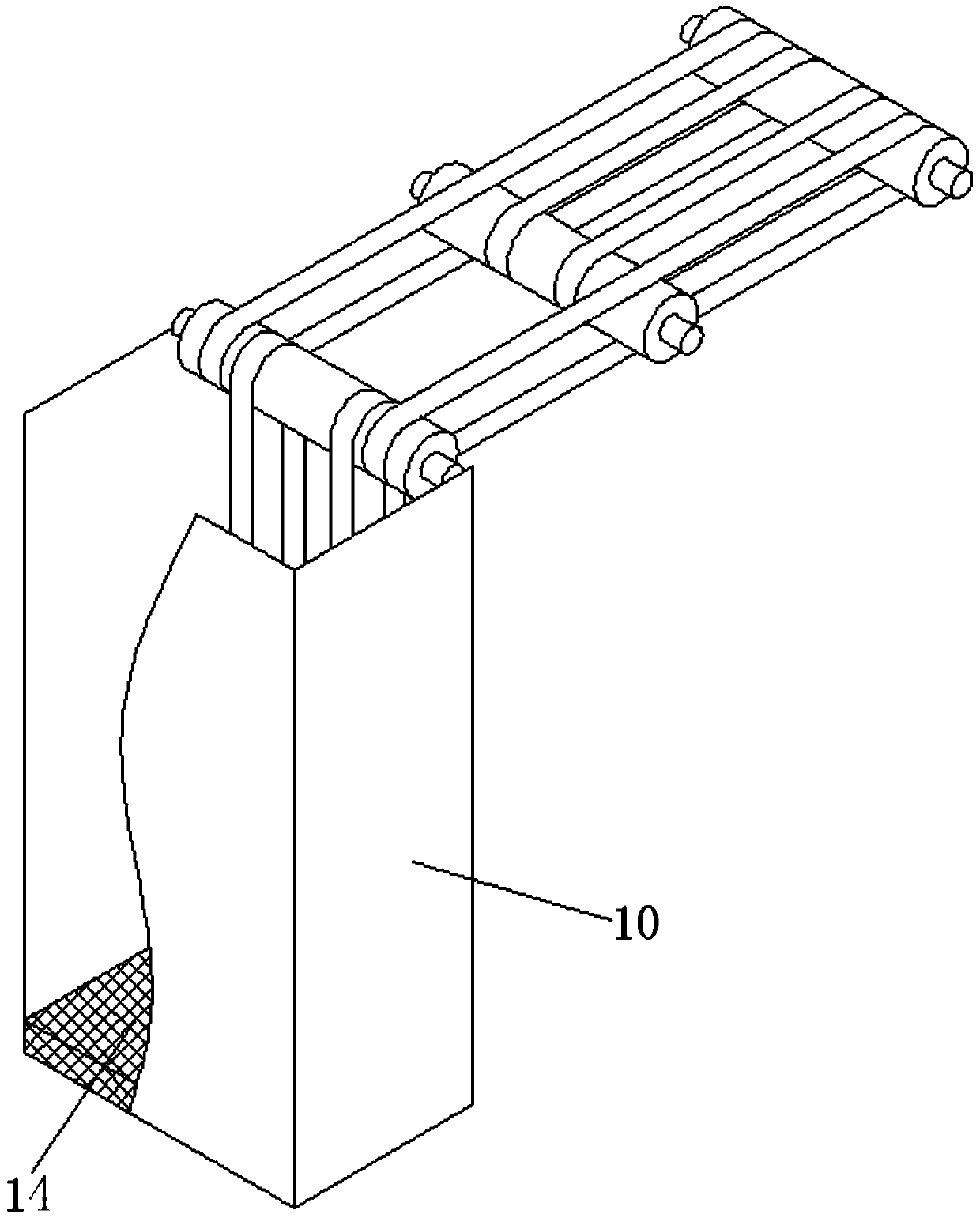
[0034] In order to achieve the purpose of the present invention, a swing conveyor belt for heat sinks includes: a horizontal conveyor belt with a first conveyor belt 6 connecting the power roller 1 and a horizontal roller 3, and the first conveyor belt 6 is transmitted in the horizontal direction; the swing conveyor belt is equipped with a connecting The second conveyor belt 5 of the power roller 1 and the swing roller 2; the blanking box 10 is arranged in parallel with the connection direction of the power roller 1 and the swing roller 2, the blanking box 10 is connected with a swing motor, and the blanking box 10 is equipped with a heat sink for accommodating cavity; the swing roller is fixedly connected with the blanking box, the swing motor drives the blanking box, the swing roller swings along the axis of the power roller itself, the blanking box and the...


PUM


Abstract

The invention discloses a pendulant conveying belt applied to heat dissipation fins. The pendulant conveying belt comprises horizontal conveying belts, pendulant conveying belts and a blanking box, wherein the horizontal conveying belts comprise first conveying belts used for connecting a power roller and a horizontal roller; the first conveying belts are used for conveying along a horizontal direction; the pendulant conveying belts comprise second conveying belts used for connecting the power roller and a pendulation roller; the blanking box is parallel to a direction of a connection line between the power roller and the pendulation roller, is connected with a pendulation motor and is provided with a cavity for receiving heat dissipation fins; the pendulation roller is fixedly connected with the blanking box; the pendulation motor is used for driving the blanking box and the pendulation roller to pendulate along a direction of a self axis of the power roller; the blanking box and thesecond conveying belts are enclosed to form a cuboid with an opening; the pendulation motor is used for driving the blanking box to pendulate in a 90-degree included angle of a direction from verticalto horizontal; the opening direction is changed in an upward direction and a horizontal direction along with pendulation of the blanking box. Through the adoption of the pendulant conveying belt applied to the heat dissipation fins, the heat dissipation fins which are vertically blanked are converted to be horizontally conveyed; the conveying manner is changed; the pendulant conveying belt is high in conveying efficiency and free of damage to the heat dissipation fins.

Description

technical field [0001] The invention relates to the field of conveyor belts, in particular to a swing conveyor belt for cooling fins. Background technique [0002] At present, the outer contour of the main body of the heat sink processed by the continuous die is in the shape of a cuboid, and the cuboid heat sink is vertically blanked due to the shape, so that the position of the heat sink after blanking is disordered, and it is easy to cause drop damage to the heat sink. It is not convenient for subsequent stacking and collection of heat sinks, and it is also not conducive to subsequent processing of heat sinks. Contents of the invention [0003] The problem to be solved by the present invention is to provide a oscillating conveyor belt for the cooling fins, the cooling fins that are dropped vertically are transformed into horizontal transmission, the transmission mode is changed, the transmission efficiency is high, and the cooling fins will not be damaged. [0004] In o...

Claims


Application Information

Patent Timeline
Patent Type & Authority Patents(China)
IPC IPC(8): B65G47/24B65G43/08
CPCB65G43/08B65G47/24
Inventor 钱同平
Owner KUNSHA KEMO PRECISION MACHINE
Why Eureka
Try Eureka