

Desktop computer display screen lifting and rotating device
A desktop computer, lifting and rotating technology, applied in the field of lifting equipment, can solve the problems that it is inconvenient for inspectors to observe the display screen from multiple directions and angles, unable to meet the needs of multi-directional and multi-angle observation, and unable to adjust the height. The effect of low production costs and high mobility
- Summary
- Abstract
- Description
- Claims
- Application Information
AI Technical Summary
Problems solved by technology
Method used
Image

Examples
Embodiment Construction
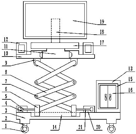
[0018] Such as figure 1 As shown, this specific embodiment adopts the following technical solutions: a desktop computer display screen lifting and rotating device, including a display screen 19, and also includes a universal wheel 1, a universal wheel support rod 2, a device base 3, and a first hydraulic cylinder 4 , the first hydraulic rod 5, the slider 6, the lifting frame connecting shaft 7, the lifting frame 8, the supporting platform connecting shaft 9, the supporting platform 10, the rotating device 11, the loudspeaker 12, the cooling main box 13, the guide rail groove 14, the sealing ring 15 , switch door 16, display screen support platform 17, display screen fixed rod 18, second hydraulic cylinder 20 and second hydraulic rod 21; both sides of the lower surface of the device base 3 are fixedly connected with universal wheel support rods 2, The bottom of the universal wheel support bar 2 is movably connected with a universal wheel 1; the right side of the device base 3 i...
PUM
 Abstract
Description
Claims
Application Information