Tire glue piece rolling and turning-over device

A technology of flipping device and film, applied in the field of tire production, can solve problems such as troublesome film connection, peeling of film and rubber strip, etc.

Pending Publication Date: 2018-08-24
DOUBLE COIN GRP JIANGSU TIRE
0 Cites 0 Cited by

AI-Extracted Technical Summary

Problems solved by technology

[0003] The technical problem to be solved by the present invention is to provide a tire film calendering and turning device, which can solve the problem that in the general tir...

Abstract

The invention relates to a tire glue piece rolling and turning-over device. The tire glue piece rolling and turning-over device comprises a conveying rack, glue guide conveying rolls, a glue pressingrolling disc, glue piece supporting racks and a glue piece turning-over roll group. The face, provided with a glue strip in a pressed manner, of a glue piece is turned over to face downwards before the glue piece and the glue strip are cut off, lifting and primary laterally turning of the glue piece are realized through a first glue piece turning-over roll, and complete turning-over and guide of the glue piece are realized through the first glue piece turning-over roll and a second glue piece turning-over roll set, so that in the cutting-off process, the glue piece and the glue strip at the cut-off position of the glue piece are not prone to be stripped off due to squeezing and cutting of a cutter. The first glue piece turning-over roll is driven through cooperation between a drive motor and a speed reducer to provide partial power for movement of the glue piece, the interval between the glue piece supporting racks is adjusted according to the ductility and breadth of different glue pieces, the initial angle of the first glue piece turning-over roll is selected, and adopted turning-over roll units reflect diversity and universality of turned-over glue materials of the device.

Technology Topic

DuctilityDrive motor +1

Image

  • Tire glue piece rolling and turning-over device

Examples

  • Experimental program(1)

Example Embodiment

[0016] The following embodiments can make those skilled in the art understand the present invention more comprehensively, but do not limit the present invention to the scope of the described embodiments.
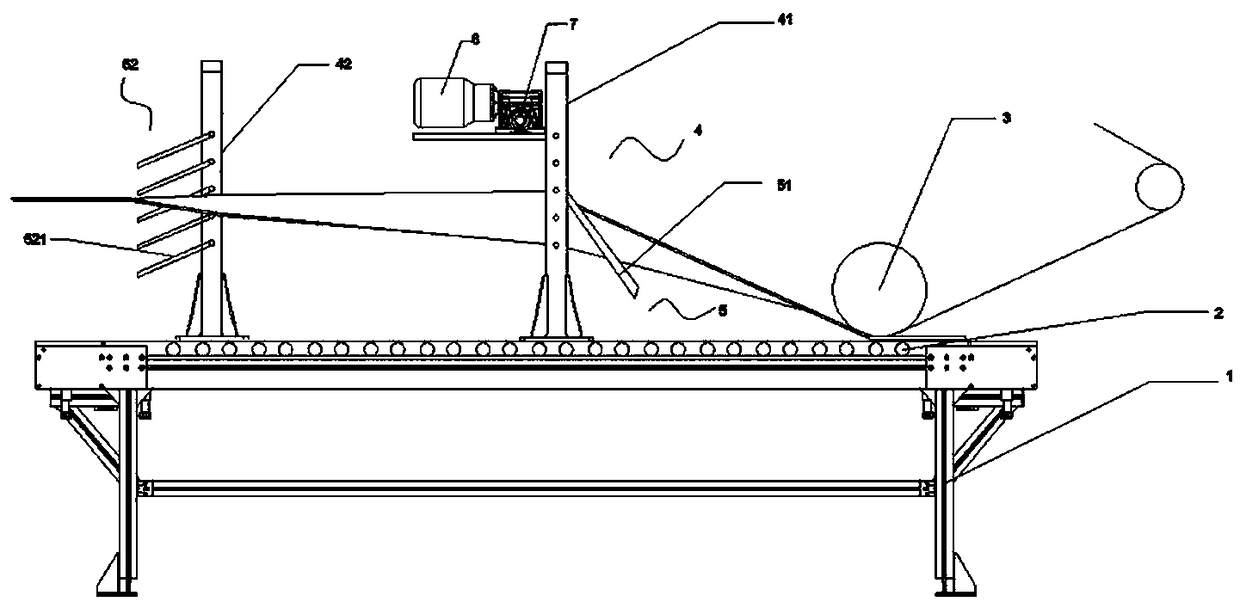
[0017] like figure 1 The shown tire film calendering and overturning device includes a conveying frame 1 , a rubber guiding conveying roller 2 , a gluing roller 3 , a film supporting frame 4 and a film turning roller group 5 .
[0018] The conveying frame 1 is arranged horizontally; the glue guiding conveying rollers 2 are arranged on the conveying frame 1 at equal intervals along the extending direction of the conveying frame 1 ; Above the glue conveying roller 2, there is a gap for accommodating the film to pass through between the gluing roller plate 3 and the glue guiding conveying roller 2, and a glue strip is arranged on the gluing roller plate 3.
[0019] The film support frame 4 has a pair including a first film support frame 41 and a second film support frame 42. The first film support frame 41 and the second film support frame 42 are respectively arranged on the conveying frame along the extending direction of the conveying frame 1. 1, the distance between the first film support frame 41 and the second film support frame 42 can be adjusted along the direction of the conveying frame 1.
[0020] The film reversing roller group 5 includes a first film reversing roller 51 and a second film reversing roller group 52, the first film reversing roller 51 is obliquely arranged on the first film supporting frame 41, and the first film reversing roller 51 can be along the The height of the first film support frame 41 is adjusted in the vertical direction; the second film turning roller group 52 includes a plurality of turning roller units 521, and the turning roller units 521 are obliquely arranged on the second film along the vertical direction through the slewing bearing. on the film support frame 42.
[0021] The first film support frame 41 is provided with a drive motor 6 and a reducer 7, the drive motor 6 is connected with the reducer 7, and the output end of the reducer 7 is connected with the first film reversing roller 51 to drive the first film reversing roller 51 to rotate. .
[0022] The adjustment range of the included angle between the first film reversing roller 51 and the horizontal direction is -30° to 30°; the reversing roller units 521 are arranged on the second film supporting frame 42 at equal intervals.
[0023] The rotational linear speed of the first film reversing roller 51 is greater than the film moving speed.
[0024] Those skilled in the art should understand that the present invention is not limited by the above-mentioned embodiments, and the descriptions in the above-mentioned embodiments and the description are only to illustrate the principle of the present invention. Without departing from the spirit and scope of the present invention, the present invention will have Various changes and modifications fall within the scope of the claimed invention. The claimed scope of the present invention is defined by the appended claims and their equivalents.

PUM

no PUM

Description & Claims & Application Information

We can also present the details of the Description, Claims and Application information to help users get a comprehensive understanding of the technical details of the patent, such as background art, summary of invention, brief description of drawings, description of embodiments, and other original content. On the other hand, users can also determine the specific scope of protection of the technology through the list of claims; as well as understand the changes in the life cycle of the technology with the presentation of the patent timeline. Login to view more.
Why Eureka
Try Eureka