An Air Flight/Land Travel Amphibious Mode Switching Mechanism for Unmanned Aerial Vehicles

A technology of unmanned driving and mode conversion, which is applied in the direction of unmanned aircraft, aircraft, and vehicles that can be converted into airplanes, etc. It can solve the problems of being unable to travel on the ground, unable to realize the conversion of air flight/land travel amphibious mode, etc.

Active Publication Date: 2019-02-26
黑龙江惠达科技股份有限公司
View PDF5 Cites 0 Cited by
  • Summary
  • Abstract
  • Description
  • Claims
  • Application Information

AI Technical Summary

Problems solved by technology

[0004] The purpose of the present invention is to solve the technical problems that the unmanned aerial vehicles in the prior art generally only fly in the air, cannot travel on the ground, and cannot realize the conversion of air flight / land travel amphibious mode, and provide an unmanned aerial vehicle that flies in the air / land. Technical scheme of amphibious mode conversion mechanism for land travel

Method used


Image

  • An Air Flight/Land Travel Amphibious Mode Switching Mechanism for Unmanned Aerial Vehicles
  • An Air Flight/Land Travel Amphibious Mode Switching Mechanism for Unmanned Aerial Vehicles
  • An Air Flight/Land Travel Amphibious Mode Switching Mechanism for Unmanned Aerial Vehicles

Examples


specific Embodiment approach 1

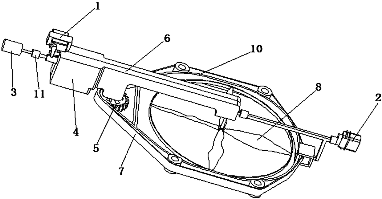
[0027] Specific implementation mode one, see figure 1 This embodiment will be described. An air flight / land travel amphibious mode conversion mechanism for unmanned aerial vehicles described in this embodiment, the conversion mechanism includes a motor 3, a reducer box 4, blades 8 and a support frame 10; it is characterized in that: The conversion mechanism also includes a left steering gear 1, a right steering gear 2, a crawler gear 5, a frame 6 and a crawler belt 7;

[0028] The left steering gear 1 and the right steering gear 2 are respectively located on the left and right sides of the frame 6, the drive shaft of the paddle 8 is fixed below the frame 6, and the paddle 8 is located at the center of the support frame 10, And both are located in the same plane, and the support frame 10 is fixedly connected with the frame 6;

[0029] The crawler gear 5 is fixed below the frame 6, the crawler gear 5 and the support frame 10 are located in the same plane, and the rotation axis...

specific Embodiment approach 2

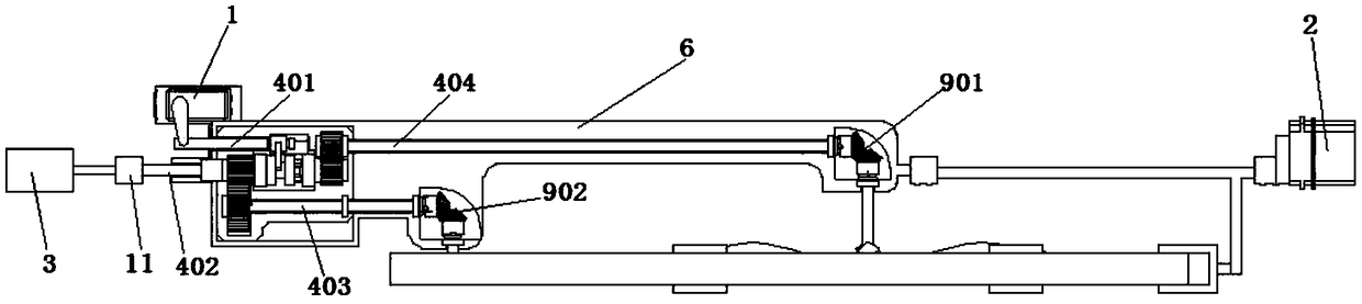
[0035] Specific implementation mode two, see Figure 5 This embodiment will be described. This embodiment is a further limitation of the air flight / land travel amphibious mode conversion mechanism for unmanned aerial vehicles described in the first embodiment. In this embodiment, the blades 8 are eight-inch paddles, and the blades 8 External fixed connection hub.

[0036] The hub plays the role of protecting the paddle 8 .

specific Embodiment approach 3

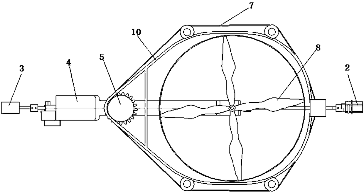
[0037] Specific implementation mode three, see figure 1 This embodiment will be described. This embodiment is a further limitation of the air flight / land travel amphibious mode conversion mechanism for unmanned aerial vehicles described in the first specific embodiment. In this embodiment, the support frame 10 is provided with crawler clips, and the The crawler clamps are fixedly connected under the frame 6, and are used for the fixed connection of the frame 6 and the support frame 10 while separating the track 7 from the support frame 10.

[0038] When the right side steering gear 1 controls the frame 6 to twist, the frame 6 and the support frame 10 are fixedly connected by crawler clips, and the support frame 10 twists along with the frame 6 torsion.


PUM


Abstract

An air flight / land travel amphibious mode conversion mechanism for unmanned aerial vehicles solves the technical problem that unmanned aerial vehicles generally only fly in the air and cannot realize the air flight / land travel amphibious mode conversion in the prior art. The steering gear of the conversion mechanism is respectively located on the left and right sides of the frame, the drive shaft of the paddle is fixed under the frame, the support frame is fixedly connected with the frame, the crawler gear is fixed under the frame, the crawler is sleeved on the support frame and the crawler gear, and the motor The output shaft of the reducer box is connected to the motor input shaft of the reducer box, and the left servo is used to control the synchronizer in the reducer box so that the motor input shaft of the reducer box is connected to output shaft one or output shaft two; output shaft two is used for Drive the crawler gear to rotate, output shaft 1 is used to drive the blade to rotate, and the right steering gear is used to drive the frame to rotate 90°, so that the plane where the blade is located is perpendicular to the ground. The invention has the advantages of ensuring the flight safety of the unmanned aerial vehicle and improving work efficiency.

Description

technical field [0001] The invention relates to an air flight / land travel amphibious mode switching mechanism, which belongs to the technical field of power devices. Background technique [0002] An unmanned aerial vehicle is an unmanned aerial vehicle mainly controlled by radio remote control or by its own program. Its successful development and market application have opened a new chapter of "non-contact communication" dominated by long-distance flying unmanned intelligent transportation tools and information-based controlled aircraft. Compared with manned aircraft, it has the advantages of small size, low cost, convenient use, low requirements on the flying environment, and strong anti-destructive ability, and is favored by inventors from all over the world. In recent years, unmanned aerial vehicles have played an important role in many fields such as shooting, inspection, transportation and search due to their advantages of accuracy, efficiency and flexibility. [0003...

Claims


Application Information

Patent Timeline
Patent Type & Authority Patents(China)
IPC IPC(8): B60F5/02B64C27/20
CPCB64C27/20B60F5/02B64U10/13B64U50/19
Inventor 韦常柱浦甲伦琚啸哲刁尹王铭泽
Owner 黑龙江惠达科技股份有限公司
Why Eureka
Try Eureka