
Expander for examining gynecological diseases

A technology for gynecological diseases and dilators, which is applied in the field of dilators for gynecological diseases examination, can solve problems such as inconvenience in use, obstruction of colposcopes or surgical instruments, and unstable expansion of dilators.

Pending Publication Date: 2018-08-28
JILIN UNIV
View PDF2 Cites 1 Cited by
  • Summary
  • Abstract
  • Description
  • Claims
  • Application Information

AI Technical Summary

Problems solved by technology

[0002] Vaginal dilators are often used during gynecological examinations, but most of today’s vaginal dilators are composed of two expansion plates and a handle, and such dilators are not stable after dilating during use, which often causes damage to the vagina. Mirrors or surgical instruments are obstructed, and the old-fashioned vaginal dilators need to be manually squeezed and then manually locked when they are opened, which makes it extremely inconvenient to use. Therefore, we propose a dilator for gynecological diseases. device

Method used


Image

  • Expander for examining gynecological diseases
  • Expander for examining gynecological diseases
  • Expander for examining gynecological diseases

Examples


no. 1 example

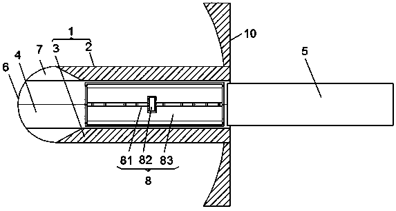
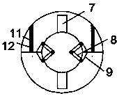
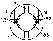
[0028] see figure 1 , figure 2 , image 3 , Figure 4 and Figure 5 , the present invention provides a technical solution: a dilator for gynecological disease inspection, including a housing 1, the housing 1 is composed of an upper half shell 2 and a lower half shell 3, and the upper half shell 2 and the lower half shell A circular cavity 4 is provided in the middle of the joint of the half shell 3, and a stretching device 5 for stretching the upper half shell 2 and the lower half shell 3 is inserted in the circular cavity 4, and the upper half shell 2 and the lower half shell 3 The right end of the lower half-shell 3 is integrally formed with a plug 6, and the two plugs 6 are fitted together to form a hemispherical shape. The middle part of the inner side wall of the two plugs 6 is provided with a tapered groove 7. The upper half-shell The front end and rear end of the bottom surface of 2 are all rotatably connected with one end of hinge plate 8, and the other end of sai...

no. 2 example

[0037] see figure 1 , figure 2 , image 3 , Figure 6 and Figure 7 , the present invention provides a technical solution: a dilator for gynecological disease inspection, including a housing 1, the housing 1 is composed of an upper half shell 2 and a lower half shell 3, and the upper half shell 2 and the lower half shell A circular cavity 4 is provided in the middle of the joint of the half shell 3, and a stretching device 5 for stretching the upper half shell 2 and the lower half shell 3 is inserted in the circular cavity 4, and the upper half shell 2 and the lower half shell 3 The right end of the lower half-shell 3 is integrally formed with a plug 6, and the two plugs 6 are fitted together to form a hemispherical shape. The middle part of the inner side wall of the two plugs 6 is provided with a tapered groove 7. The upper half-shell The front end and rear end of the bottom surface of 2 are all rotatably connected with one end of hinge plate 8, and the other end of sai...


PUM


Abstract

The invention discloses an expander for examining gynecological diseases. The expander comprises a shell, the shell is composed of an upper half shell and a lower half shell which fit each other, anda circular cavity is formed in the middle of the fitting portion of the upper half shell and the lower half shell; a spreading device used for spreading the upper half shell and the lower half shell is inserted into the circular cavity, top heads are integrally formed in the right ends of the upper half shell and the lower half shell, and the front and rear ends of the bottom face of the upper half shell are rotatably connected with the ends of hinge plates; the other end of each hinge plate is rotatably connected with the upper surface of the lower half shell, limit clamping grooves are formed in the rotation junction between the upper half shell and one hinge plate and the rotation junction between the lower half shell and the other hinge plate, and top plates are fixedly connected to the right ends of the upper half shell and the lower half shell. Through the application of the upper half shell, the lower half shell, the limit clamping grooves and the hinge plates, the expander hasthe advantage of stable spreading, and meanwhile the functions of convenient spreading and automatic locking are achieved through application of the spreading device and the hinge plates.

Description

technical field [0001] The invention relates to the technical field of obstetrics and gynecology medical devices, in particular to a dilator for gynecological disease inspection. Background technique [0002] Vaginal dilators are often used during gynecological examinations, but most of today’s vaginal dilators are composed of two expansion plates and a handle, and such dilators are not stable after dilating during use, which often causes damage to the vagina. Mirrors or surgical instruments are obstructed, and the old-fashioned vaginal dilators need to be manually squeezed and then manually locked when they are opened, which makes it extremely inconvenient to use. Therefore, we propose a dilator for gynecological diseases. device. Contents of the invention [0003] The object of the present invention is to provide a dilator for examining gynecological diseases, so as to solve the problems raised in the above-mentioned background technology. [0004] In order to achieve ...

Claims


Application Information

Patent Timeline
Patent Type & Authority Applications(China)
IPC IPC(8): A61B1/32
CPCA61B1/32
Inventor 魏敏吕春香侯秀伟
Owner JILIN UNIV
Learn More