
Centrifugal wind wheel and air conditioner indoor unit

A technology for air-conditioning indoor units and centrifugal wind wheels, which is applied to mechanical equipment, machines/engines, liquid fuel engines, etc., can solve problems such as uneven air output, and achieve the effect of improving the uniformity of air output and reducing the noise of air output

Pending Publication Date: 2018-08-28
GD MIDEA AIR-CONDITIONING EQUIP CO LTD
View PDF0 Cites 5 Cited by
  • Summary
  • Abstract
  • Description
  • Claims
  • Application Information

AI Technical Summary

Problems solved by technology

[0004] The main purpose of the present invention is to provide a centrifugal wind wheel, aiming to solve the problem of uneven wind

Method used


Image

  • Centrifugal wind wheel and air conditioner indoor unit
  • Centrifugal wind wheel and air conditioner indoor unit
  • Centrifugal wind wheel and air conditioner indoor unit

Examples


Embodiment Construction

[0031] The following will clearly and completely describe the technical solutions in the embodiments of the present invention with reference to the accompanying drawings in the embodiments of the present invention. Obviously, the described embodiments are only part of the embodiments of the present invention, not all of them. Based on the embodiments of the present invention, all other embodiments obtained by persons of ordinary skill in the art without creative efforts fall within the protection scope of the present invention.

[0032] It should be noted that all directional indications (such as up, down, left, right, front, back...) in the embodiments of the present invention are only used to explain the relationship between the components in a certain posture (as shown in the accompanying drawings). Relative positional relationship, movement conditions, etc., if the specific posture changes, the directional indication will also change accordingly.

[0033] In addition, the ...


PUM


Abstract

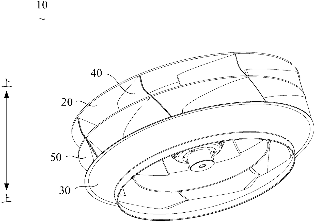
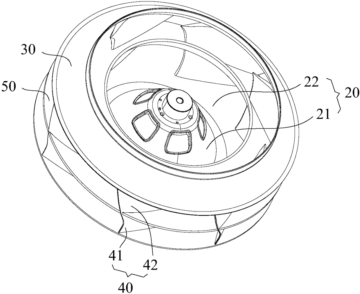
The invention discloses a centrifugal wind wheel and an air conditioner indoor unit. The centrifugal wind wheel comprises a blade seat, a first air inducing ring and a plurality of fan blades connecting the blade seat with the first air inducing ring. The centrifugal wind wheel further comprises a second air inducing ring, the second air inducing ring is located between the blade seat and the first air inducing ring, and the fan blades penetrate through the second air inducing ring to be connected with the second air inducing ring. The second air inducing ring is provided with a first end opening and a second end opening, wherein the first end opening and the second end opening are formed oppositely. The first end opening of the second air inducing ring is close to the blade seat, and thediameter of the second air inducing ring is gradually reduced in the direction from the first end opening to the second end opening. By means of the centrifugal wind wheel and the air conditioner indoor unit, the air-out uniformity of the centrifugal wind wheel is improved.

Description

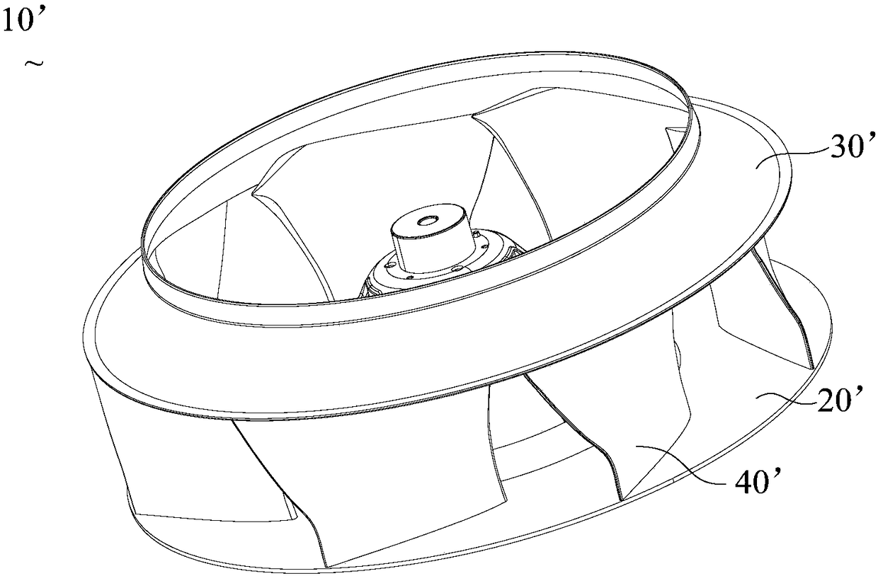
technical field [0001] The invention relates to the technical field of air conditioning, in particular to a centrifugal wind wheel and an air conditioning indoor unit. Background technique [0002] see figure 1 , the existing centrifugal wind wheel 10' generally includes a blade seat 20', a first wind-inducing ring 30' and a fan blade 40'. Wherein, the fan blade 40' is fixed between the blade seat 20' and the first wind-inducing ring 30', and when the centrifugal wind wheel 10' rotates, the airflow enters from the middle of the first wind-inducing ring 30', and then passes through the fan blade 40' to be discharged from the air passage formed between the blade base 20' and the first wind-inducing ring 30'. [0003] However, most of the air flow formed by the above-mentioned centrifugal wind wheel 10' is discharged from the surface of the blade seat 20', and only a small amount of air flow is discharged along the surface of the first wind-inducing ring 30' (towards the surf...

Claims


Application Information

Patent Timeline
IPC IPC(8): F04D29/28F04D29/44F04D29/66
CPCF04D29/281F04D29/441F04D29/666
Inventor 凌敬刘乾坤季振勤
Owner GD MIDEA AIR-CONDITIONING EQUIP CO LTD
Learn More