Milling Cutter Holding Equipment

A technology for clamping equipment and milling cutters, applied in the direction of metal processing equipment, clamping, clamping devices, etc., to reduce the probability of damage, avoid the tilting of milling cutters, and avoid the effects of adjustment

Active Publication Date: 2019-06-04
宁波隆锐机械制造有限公司
View PDF1 Cites 0 Cited by
  • Summary
  • Abstract
  • Description
  • Claims
  • Application Information

AI Technical Summary

Problems solved by technology

[0005] The technical problem solved by the present invention is to provide a milling cutter clamping device to solve the problem that the existing milling cutter clamping device cannot automatically detect whether the milling cutter is offset and automatically clamp the offset milling cutter

Method used


Image

  • Milling Cutter Holding Equipment
  • Milling Cutter Holding Equipment
  • Milling Cutter Holding Equipment

Examples


Embodiment 1

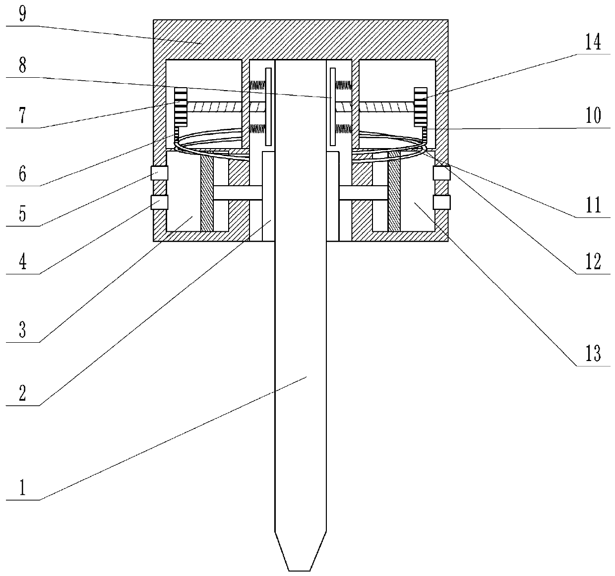
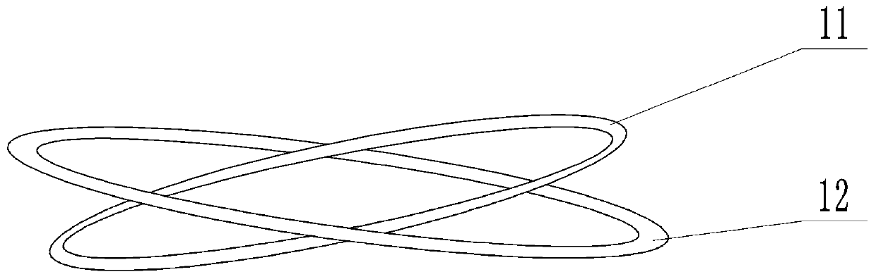
[0028] The embodiment is basically as attached figure 1 And attached figure 2Shown: milling cutter clamping equipment, including a frame 9, the center of the frame 9 is provided with a passage for the milling cutter 1 to pass through, and the top of the passage is provided with a pentagonal blind hole matching the shape of the top end of the milling cutter 1. The side is provided with an adjustment chamber and a cylinder from top to bottom. A clamping plate 2 for clamping and fixing the milling cutter 1 is fixedly installed on the piston rod of the cylinder. The contact surface between the clamping plate 2 and the milling cutter 1 is an arc surface , the cylinder includes the first cylinder 3 on the left side of the milling cutter 1 and the second cylinder 13 on the right side, and the upper side walls of the first cylinder 3 and the second cylinder 13 are respectively provided with venting ports 17 for gas in and out; The side wall is provided with a detection piece 8 for c...

Embodiment 2

[0035] as attached image 3 As shown, the difference between the second embodiment and the first embodiment is that there is no annular slideway, the first slide ring 12 and the second slide ring 11 in the second embodiment, the left side wall of the first cylinder 3 and the right side of the second cylinder 13 There is an air release port 17 on the side wall, and the shaft 16 of the first pinion 6 and the second pinion 10 is connected with an eccentric wheel 15 covering the air release port 17. The connecting pipe 19 (attached image 3 The second cylinder 13, the second pinion 10, etc. are not all drawn).

[0036] During specific implementation, if the installed milling cutter 1 deviates to the left, the rotation of the first pinion 6 will cause the eccentric wheel 15 connected on the rotating shaft 16 of the first pinion 6 to deflect, and the eccentric wheel 15 will deflect to make the air release port 17 Open, the gas in the high-pressure gas tank enters the first cylinde...


PUM


Abstract

The invention relates to the field of positioning of milling cutters, in particular to clamping equipment for a milling cutter. The clamping equipment comprises a rack, wherein a channel into which the milling cutter penetrates is arranged in the center of the rack; a pentagonal blind hole matched with a pentagonal cylinder arranged at the top end of the milling cutter is formed in the top end ofthe channel; air cylinders are respectively arranged on the two sides of the channel; clamping plates for clamping and fixing the milling cutter are arranged on piston rods of the air cylinders; manual charging valves are arranged on the air cylinders; adjusting chambers are separately arranged on the air cylinders; threaded holes are formed in side walls, close to the milling cutter, of the adjusting chambers; the aside parts of the threaded holes are connected with springs; the springs are connected with detection plates which are used for clamping the milling cutter and detecting whether the milling cutter is inclined or not; the detection plates are connected with a threaded rod in a rotating manner; the threaded rod penetrates through the threaded holes and enters into the adjusting chambers; the threaded rod is positioned at one end of the inner part of an adjusting channel and a big gear are fixedly mounted on the threaded rod; and adjustment mechanisms which are driven by the big gear so as to automatically adjust the milling cutter when the milling cutter is inclined are arranged in the adjusting chambers.

Description

technical field [0001] The invention relates to the field of milling cutter positioning, in particular to a milling cutter clamping device. Background technique [0002] A milling cutter is a rotating tool with one or more teeth for milling operations. When working, each knife tooth cuts off the allowance of the workpiece intermittently in turn. Milling cutters are mainly used for machining planes, steps, grooves, forming surfaces and cutting off workpieces on milling machines. It plays an important role in the processing of mechanical equipment. The milling cutter often needs to be clamped first when it is working. [0003] The Chinese patent document with publication number CN106956028A discloses a milling cutter clamping device that is easy to install, including a clamping seat, a milling cutter shank fixed on the clamping seat, and a milling cutter head connected to the lower end of the milling cutter shank , the milling cutter shank and the milling cutter head are c...

Claims


Application Information

Patent Timeline
Patent Type & Authority Patents(China)
IPC IPC(8): B23Q3/12B23Q5/26
CPCB23Q3/12B23Q5/26B23Q2703/04
Inventor 叶敏
Owner 宁波隆锐机械制造有限公司
Why Eureka
Try Eureka