[0016] Combine below Figure 1-4 The present invention will be described in detail.
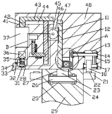
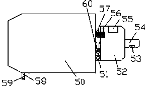
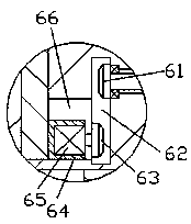
[0017] Reference Figure 1-4 According to an embodiment of the present invention, an environmentally-friendly high-efficiency purifying faucet includes a fixing frame 48 that is rotatably fitted on the pole 29 and an outlet faucet 50 that is locked and connected to the fixing frame 48. The fixing frame A first insertion cavity 37 is provided in the left end surface of 48, a second insertion cavity 71 is provided in the right inner wall of the first insertion cavity 37, and a first sliding cavity 41 is provided in the top wall of the first insertion cavity 37 A first sliding plate 42 is installed in the first sliding cavity 41 in a sliding fit, a second sliding cavity 44 extends left and right in the right inner wall of the first sliding cavity 41, and the second sliding cavity 44 is slidingly fit A second sliding plate 43 integrated with the first sliding plate 42 is installed, and a third sliding cavity 75 extends up and down in the inner bottom wall of the second sliding cavity 44 on the right side of the first insertion cavity 37 The third sliding cavity 75 is slidingly fitted with a third sliding plate 73 whose top end is fixedly connected to the bottom end surface of the second sliding plate 43, and a first tooth is provided in the right end surface of the third sliding plate 73 A bar 72, the left end of the third sliding cavity 75 is provided with a power connection device extending into the second insertion cavity 71, and a first transmission cavity 46 is provided in the right inner wall of the third sliding cavity 75, The first transmission cavity 46 is rotatably provided with a first toothed wheel 45 meshing with the first toothed bar 72. The rear end of the first toothed wheel 45 is power connected with a first motor, so The outer surface of the first motor is fixed in the inner wall of the rear side of the first transmission cavity 46. A fourth sliding cavity 47 extends up and down in the right inner wall of the first transmission cavity 46. A fourth sliding plate 12 is installed in a sliding fit. The left end surface of the fourth sliding plate 12 is provided with a second toothed bar 11 meshing with the first toothed wheel 45. The fourth sliding cavity 47 right A fifth sliding cavity 66 is connected to the lower side of the side inner wall, and a fifth sliding plate 64 whose left end surface is fixedly connected with the right end surface of the fourth sliding plate 12 is installed in the fifth sliding cavity 66 in sliding fit. A second transmission cavity 62 extends up and down in the right inner wall of the fifth sliding cavity 66, a second electric motor 65 is fixedly arranged in the right end surface of the fifth sliding plate 64, and the right end of the second electric motor 65 has power A first conical wheel 63 extending into the second transmission cavity 62 is connected. The fixing frame 48 on the right side of the second transmission cavity 62 is provided with a third transmission cavity 13 with an opening facing downwards. A first steering shaft 14 is rotatably installed on the upper side of the third transmission cavity 13. The left-side extension end of the first steering shaft 14 extends into the second transmission cavity 62, and the end is fixedly provided with the first steering shaft. A second tapered wheel 61 is engaged with a tapered wheel 63, and a second steering shaft 15 is rotatably connected in the third transmission cavity 13 on the lower side of the first steering shaft 14. The second steering shaft 15 is left The side is fixedly provided with a second toothed wheel 18 protruding beyond the bottom end surface of the fixing frame 48, and a transmission belt 15 is connected between the second steering shaft 15 and the first steering shaft 14. The top end face of the upright 29 is provided with a first through cavity 27 in the center, and the first The inner bottom wall of the through cavity 27 is provided with a steering cavity 25 that is concentric with the first through cavity 27, and the bottom end surface of the fixing frame 48 is fixedly provided with a third steering shaft 23 extending into the first through cavity 27, The bottom end surface of the third steering shaft 23 is fixedly provided with a steering block 26 that is rotatably arranged in the steering cavity 25. The upper and lower end walls of the steering cavity 25 are rotatably provided with a plurality of sets of upper and lower end surfaces of the steering block 26. Abutting ball 24, the outer surface of the vertical rod 29 is fixed with a circular ring 21 in the circumferential direction, the circular ring 21, the top end of the circular ring 21 is fixed with the second toothed wheel 18 Toothed ring 22 meshing with each other.
[0018] Beneficially or illustratively, the inner wall of the fixing frame 48 on the lower side of the first insertion cavity 37 is provided with a cavity 28, and a fourth steering shaft 31 extending up and down is rotatably installed in the cavity 28, so The top end of the fourth steering shaft 31 is dynamically connected to a third electric motor 36, the outer surface of the third electric motor 36 is fixed in the inner top wall of the cavity 28, and the outer surface of the fourth steering shaft 31 is fixed circumferentially The winding reel 35 is provided with a second through cavity 32 penetrating the left end surface of the fixing frame 48 in the inner wall of the left side of the cavity 28, the winding reel 35 is fixedly provided with a draw rope 34, and the pulling The rope 34 passes through the second through cavity 32 and a hook 33 is fixed at the end, so as to facilitate the adjustment of the vertical direction of the faucet 50.
[0019] Beneficially or exemplarily, a connecting rod 58 is fixedly provided on the left side of the bottom end surface of the faucet 50, and a third through cavity 59 for the hook 33 to extend into is provided in the connecting rod 58. The faucet The right end of the 50 is provided with an insertion block 52 that is connected to the first insertion cavity 37 by plug-in fitting. The bottom of the left end of the insertion block 52 and the right end of the faucet 50 are hingedly connected by a hinge shaft 51. A wire 60 is connected between the insertion block 52 on the upper side of the hinge shaft 51 and the faucet 50, and a spring cavity 56 is provided in the left end surface of the insertion block 52 on the upper side of the wire 60. The spring cavity A pulling bar 57 is fixedly connected in 56 to the right end surface of the faucet 50, and the top end surface of the insertion block 52 is provided with a locking hole 55 that is inserted and connected to the first sliding plate 42. The right side end of the inserting block 52 is fixedly provided with an inserting rod 54 that is connected to the second inserting cavity 71 in a mating and mating manner. The bottom end of the inserting rod 54 is provided with an electrical connection piece 53 connected to the wire 60 to facilitate The faucet 50 is locked and installed and the direction is adjusted.
[0020] Beneficially or illustratively, the power connection device includes a sixth sliding cavity 81 extending left and right in the inner wall of the third sliding cavity 75, and a double inclined sliding plate 79 is slidingly fitted in the sixth sliding cavity 81. , The left end surface of the third sliding plate 73 is provided with an inclined sliding cavity 74 for the double inclined sliding plate 79 to extend, and the inner bottom wall of the sixth sliding cavity 81 is provided with a first guiding cavity 78, A first guide block 76 fixedly connected to the bottom end surface of the double-inclined sliding plate 79 is installed in the first guide cavity 78 in a sliding fit, and the first guide block 76 on the left side of the first guide block 76 A first elastic piece 77 is press-fitted in the cavity 78, and a seventh sliding cavity 88 communicating with the second insertion cavity 71 is extended up and down in the top wall of the sixth sliding cavity 81. The seventh sliding cavity In the cavity 88, an inclined sliding plate 86 which is press-fitted and connected with the double inclined sliding plate 79 is installed in the cavity 88. A second guiding cavity 85 is provided in the right inner wall of the seventh sliding cavity 88, and the second guiding A second guide block 82 fixedly connected to the right end surface of the inclined sliding plate 86 is installed in the guide cavity 85 in a sliding fit. The second guide cavity 85 on the upper side of the second guide block 82 is pressed against A second elastic sheet 83 is matched and installed, and the top end surface of the inclined sliding plate 86 is fixedly provided with a power connector 87 for abutting against the power connector 53 so as to automatically connect to the faucet 50.
[0021] In the initial state, the first sliding plate 42 completely extends into the first sliding cavity 41, the right end of the double-incline sliding plate 79 extends into the inclined sliding cavity 74, and the power connector 87 is completely in the seventh sliding cavity 88. The cone wheel 63 is disengaged from the second cone wheel 61.
[0022] When the faucet 50 needs to be installed, align the insertion block 52 with the first insertion cavity 37 and completely insert it into the first insertion cavity 37. At this time, the insertion rod 54 is completely inserted into the second insertion cavity 71, and the first motor is started to drive The first toothed wheel 45 rotates counterclockwise to make the third sliding plate 73 slide down, and the third sliding plate 73 drives the first sliding plate 42 to slide down and insert it into the locking hole 55. The third sliding plate 73 slides down at the same time The double-inclined sliding plate 79 is driven to overcome the pressing pressure of the first elastic piece 77 to slide to the left. The double-inclined sliding plate 79 slides to drive the inclined sliding plate 86 to overcome the pressing pressure of the second elastic piece 83 to slide upwards, and make the electrical connection head 87 and the connection The electric sheet 53 is completely abutted. At this time, the faucet 50 is connected and locked and installed. The first motor drives the first toothed wheel 45 to rotate counterclockwise while driving the fourth sliding plate 12 to slide upward, and the fourth sliding plate 12 Sliding upward drives the fifth sliding plate 64 to slide upwards. The upward sliding of the fifth sliding plate 64 makes the first cone wheel 63 slide upward to mesh with the second cone wheel 61, and then hook the hook 33 into the third through cavity Within 59.
[0023] When it is necessary to adjust the front, back, left, and right directions of the faucet 50, start the second motor 65 to drive the second toothed wheel 18 to rotate. Because the second toothed wheel 18 and the toothed ring 22 mesh with each other, the mounting frame 48 is along the first The three steering shafts 23 start to rotate, that is, adjust the faucet 50 to adjust the front, rear, left, and right directions. When the faucet 50 needs to be adjusted up and down, the third motor 36 is activated to drive the winding drum 35 to rotate, and the winding drum 35 pulls the rope 34 to thereby The faucet 50 is made to overcome the tensile force of the pulling bar 57 to rotate downward with the hinge shaft 51 as the center, and the downward adjustment direction of the faucet 50 can be controlled by controlling the length of the spool 35 extending.
[0024] The beneficial effects of the present invention are: since in the initial state, the first sliding plate is fully extended into the first sliding cavity, the right end of the double-inclined sliding plate extends into the inclined sliding cavity, and the electrical connection head is completely in the seventh sliding cavity , The first conical wheel is disengaged from the second conical wheel, so that the mounting frame can be adjusted manually to adjust the direction at will, which is convenient for quick installation of the faucet, and is beneficial to the protection of the electric head to prevent accidental damage.
[0025] When the faucet needs to be installed, align the insertion block with the first insertion cavity and fully insert it into the first insertion cavity. At this time, the insertion rod is fully inserted into the second insertion cavity, and the first motor is started to drive the first toothed wheel. The clockwise rotation makes the third sliding plate slide down. The third sliding plate drives the first sliding plate to slide down and insert it into the locking hole. While the third sliding plate slides down, it drives the double-inclined sliding plate to overcome the top of the first elastic sheet. The pressure slides to the left, and the sliding of the double-inclined sliding plate drives the inclined sliding plate to overcome the top pressure of the second elastic piece to slide upwards, and make the electrical connector and the electrical connector completely abut, at this time, the faucet is connected and locked and installed , The first motor drives the first toothed wheel to rotate counterclockwise while driving the fourth sliding plate to slide upwards, the fourth sliding plate slides upwards to drive the fifth sliding plate to slide upwards, and the upward sliding of the fifth sliding plate makes the first conical wheel Slide upward to engage with the second cone wheel, and then hook the hook into the third cavity, so that the faucet can be quickly locked and installed without the use of other tools, its operation is convenient, and the automatic use efficiency is high.
[0026] When you need to adjust the front, back, left, and right directions of the faucet, start the second motor to drive the second toothed wheel to rotate. Because the second toothed wheel meshes with the toothed ring, the mounting frame starts to rotate along the third steering axis. That is, adjust the faucet to start to adjust the front, back, left, and right directions. When the faucet needs to be adjusted up and down, the third motor is started to drive the winding drum to rotate, and the winding drum pulls the rope so that the faucet overcomes the tensile force of the pulling bar to hinge the shaft To rotate the center of the circle downwards, the downward adjustment direction of the faucet can be controlled by controlling the length of the spool, so that the faucet can be automatically adjusted to the front, back, left, and right, and up and down directions of the faucet, effectively increasing the use range of the faucet.
[0027] It is obvious to those skilled in the art that various modifications to the above embodiments can be made without departing from the overall spirit and concept of the present invention. All of them fall into the protection scope of the present invention. The protection scheme of the present invention is subject to the appended claims of the present invention.