Display support
A display stand and support technology, which is applied in machine/stand, supporting machine, mechanical equipment, etc., can solve the problem that the display stand cannot be lifted up and down, and achieve the effect of preventing fatigue
- Summary
- Abstract
- Description
- Claims
- Application Information
AI Technical Summary
Problems solved by technology
Method used
Image
Examples
Embodiment 1
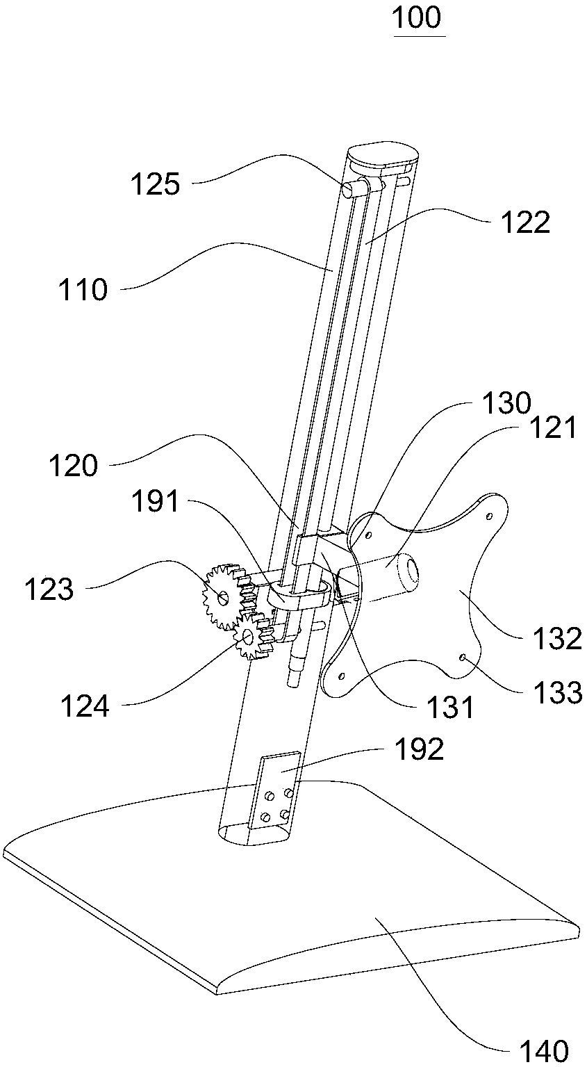
[0027] Such as figure 1 As shown, this embodiment provides a display stand 100, which includes a column 110, a lifting mechanism 120 and a mounting member 130. Wherein, the mounting member 130 is used to mount the display on the stand 100.
[0028] Specifically, the lifting mechanism 120 is installed on the column 110, and the mounting member 130 cooperates with the lifting mechanism 120 and is driven by the lifting mechanism 120 to move along the height direction of the column 110. That is, the lifting mechanism 120 can drive the mounting member 130 to move along the height direction of the column 110. That is, the mounting member 130 can move up and down along the column 110. After the mounting member 130 moves, the display mounted on the mounting member 130 can also move up and down. When the display moves up and down in the vertical direction, the user’s head and neck will also be rotated for effective viewing while watching the display, thereby realizing the movement of the ...
Embodiment 2
[0037] In this embodiment, see embodiment 1 for parts not mentioned, and the difference from embodiment 1 is:
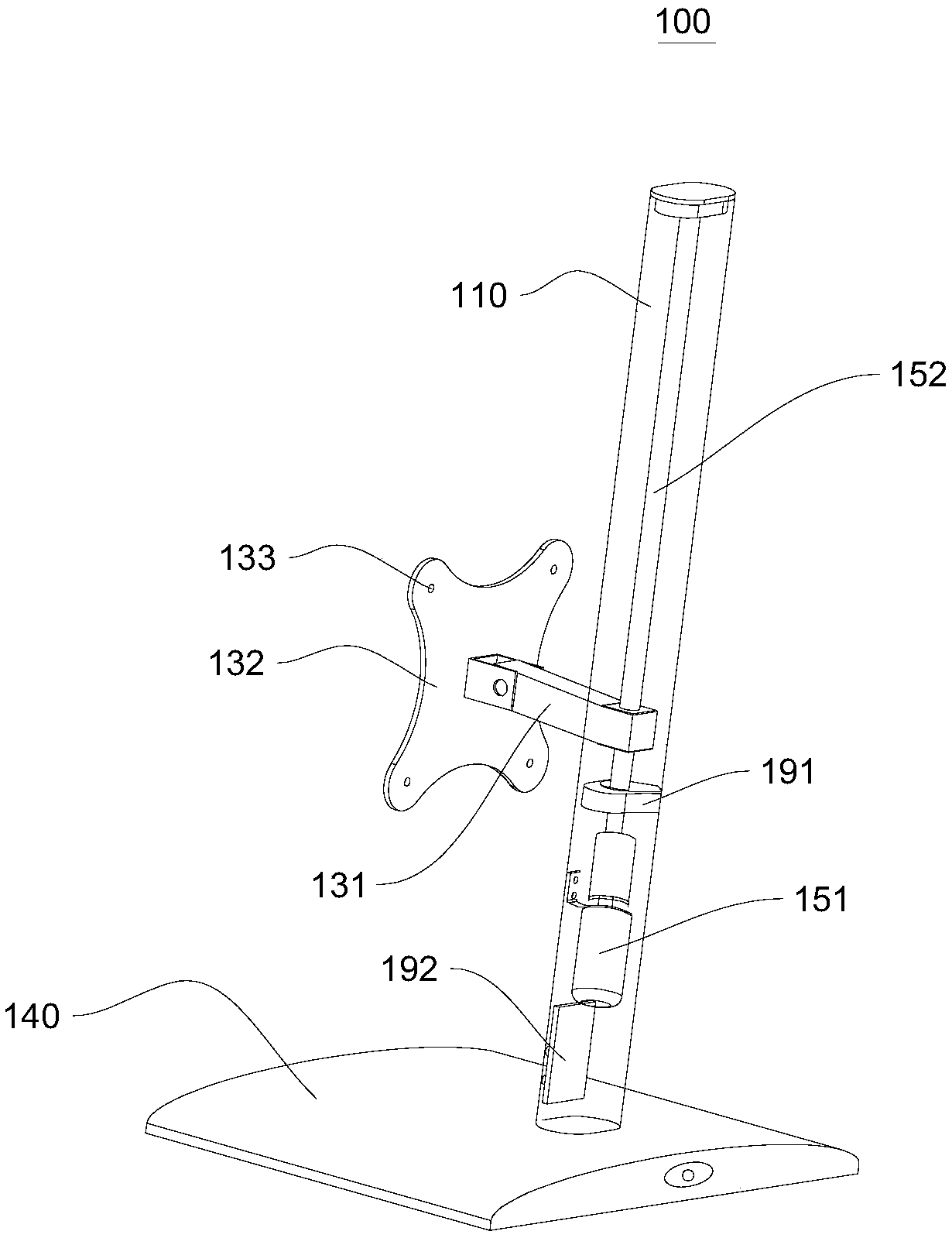
[0038] Such as figure 2 As shown, the lifting mechanism 120 includes a second driving device 151 and a threaded rod 152. The threaded rod 152 is provided on the column 110. The second driving device 151 drives the threaded rod 152 to rotate. The mounting member 130 has a threaded hole at one end close to the lifting mechanism 120. , The threaded hole is matched with the threaded rod 152; that is, the mounting member 130 converts the rotational movement of the threaded rod 152 into linear motion, that is, a mechanism similar to a "screw".
[0039] The lifting mechanism 120 also includes a limiting member 191. The limiting member 191 is sleeved on the threaded rod 152 and is sleeved with the threaded rod 152; the outer side of the limiting member 191 is fixedly connected with the column 110, and the limiting member 191 has a vertical communication Hole, the threaded rod 15...
Embodiment 3
[0041] In this embodiment, see embodiment 2 for parts not mentioned, and the difference from embodiment 2 is:
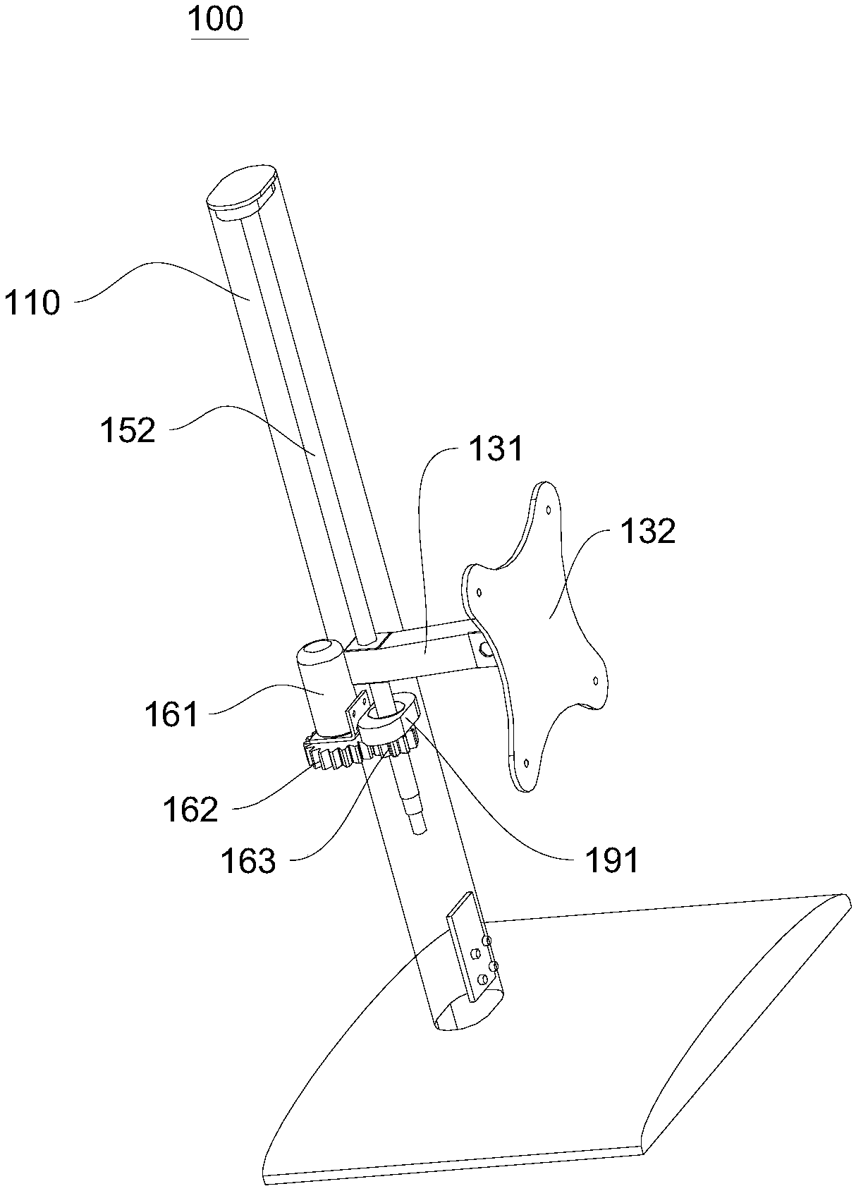
[0042] Such as image 3 As shown, the second driving device 151 includes a first motor 161, a third gear 162 and a fourth gear 163 that mesh with each other. The first motor 161 drives the third gear 162 to rotate, and the fourth gear 163 is sleeved on the outside of the threaded rod 152. And is fixedly connected with the threaded rod 152. After the first motor 161 drives the third gear to rotate, since the third gear 162 and the fourth gear 163 mesh, the fourth gear 163 will also rotate. After the fourth gear 163 rotates, it will drive the threaded rod 152 to rotate. After that, the mounting member 130 converts the rotational movement of the threaded rod 152 into linear motion and drives the display to move up and down.
PUM
 Abstract
Description
Claims
Application Information
 - R&D
- Intellectual Property
- Life Sciences
- Materials
- Tech Scout
- Unparalleled Data Quality
- Higher Quality Content
- 60% Fewer Hallucinations
Browse by: Latest US Patents, China's latest patents, Technical Efficacy Thesaurus, Application Domain, Technology Topic, Popular Technical Reports.
© 2025 PatSnap. All rights reserved.Legal|Privacy policy|Modern Slavery Act Transparency Statement|Sitemap|About US| Contact US: help@patsnap.com


