Electrical connector

An electrical connector and connecting part technology, applied in the direction of connection, two-part connection device, circuit, etc., can solve the problems of electromagnetic interference and unfavorable high-frequency signal transmission, and achieve the purpose of reducing electromagnetic interference, reducing thickness, and improving high-frequency transmission. performance effect

Active Publication Date: 2018-09-04
DEYI PRECISION ELECTRONIC IND CO LTD PANYU
View PDF7 Cites 2 Cited by
  • Summary
  • Abstract
  • Description
  • Claims
  • Application Information

AI Technical Summary

Problems solved by technology

Since each row of terminals includes ground terminals, power terminals and differential signal terminals for transmitting high-frequency signals, the number of terminals is large, and electromagnetic interference will be generated between multiple terminals during use, which is not conducive to high-frequency signals. transmission

Method used


Image

  • Electrical connector
  • Electrical connector
  • Electrical connector

Examples


Embodiment Construction

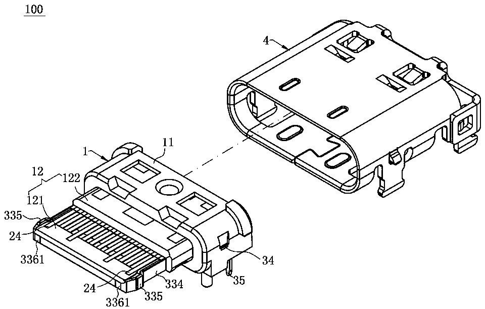
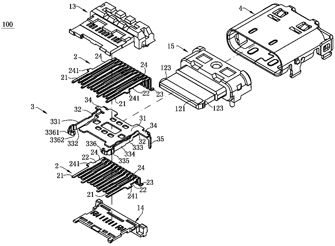
[0042] In order to facilitate a better understanding of the purpose, structure, features, and effects of the present invention, the present invention will now be further described in conjunction with the accompanying drawings and specific embodiments.

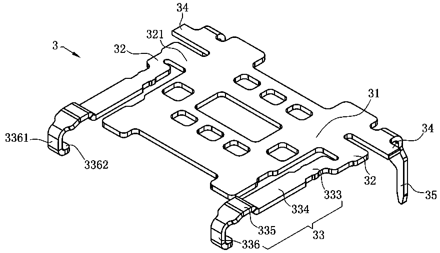
[0043] Such as figure 1 and figure 2 As shown, the electrical connector 100 of the present invention includes an insulating body 1 , upper and lower rows of terminals 2 , a shielding sheet 3 and a shielding shell 4 . The electrical connector 100 can be welded on a circuit board (not shown, the same below) under the electrical connector 100, and is used to dock with a pair of mating connectors (not shown, the same below), wherein, The docking connector has a docking cavity (not shown, the same below) and two ground elastic arms (not shown, the same below) located on the left and right sides of the docking cavity.

[0044] Such as figure 1 and figure 2 As shown, the insulating body 1 is provided with a base 11 and a tongue ...


PUM


Abstract

The present invention discloses an electrical connector including an insulation body, a shielding piece, and at least a row of terminals. The insulation body includes a base and a tongue plate extending forwardly from the base, the side of the tongue plate is provided with at least one latching groove, the shielding piece is disposed on the insulation body, the shielding piece is provided with a plate body and at least one extending portion, a connecting portion connects the plate body and the extending portion, the extending portion is located at the side of the plate body and is perpendicular to the plate body, and the extending portion comprises a lock exposed to the latching groove and a lap portion; at least one row of terminals are received in the insulation body and located on one side of the shielding piece, wherein at least one grounding terminal is disposed at the outermost side, and the grounding terminal overlaps the lap portion to realize the grounding of the grounding terminal and the shielding piece, thereby reducing the electromagnetic interference and improving the high-frequency transmission performance of the electrical connector; and the lap portion is recessed,and the overall height of the lap portion and the grounding terminal can be reduced, and the thickness of the entire tongue plate is reduced.

Description

technical field [0001] The invention relates to an electrical connector, in particular to an electrical connector with good high-frequency transmission performance. Background technique [0002] The existing USB TYPE C socket connector for transmitting high-frequency signals includes an insulating body, two rows of terminals and a shielding sheet, and the shielding sheet is located between the two rows of terminals and is fixed on the insulating body together. Since each row of terminals includes ground terminals, power terminals and differential signal terminals for transmitting high-frequency signals, the number of terminals is large, and electromagnetic interference will be generated between multiple terminals during use, which is not conducive to high-frequency signals. transmission. [0003] Therefore, it is necessary to design an improved electrical connector to overcome the above problems. Contents of the invention [0004] In view of the problems faced by the bac...

Claims


Application Information

Patent Timeline
Patent Type & Authority Applications(China)
IPC IPC(8): H01R13/6581H01R13/652H01R13/02H01R13/6597
CPCH01R13/02H01R13/652H01R13/6581H01R13/6597H01R13/502H01R13/504H01R13/516H01R13/648H01R13/6591H01R13/6585H01R2107/00H01R24/60H01R13/6594H01R24/64H01R13/639
Inventor 蔡友华
Owner DEYI PRECISION ELECTRONIC IND CO LTD PANYU
Why Eureka
Try Eureka