Screening device for gear part processing

A screening device and parts processing technology, applied in solid separation, classification, chemical instruments and methods, etc., can solve the problems of low screening efficiency of screening structures, inconvenient use of screening devices, inconvenient disassembly and replacement of parts, etc. Simple structure and strong practicability

Inactive Publication Date: 2018-09-07
李思模
0 Cites 1 Cited by

AI-Extracted Technical Summary

Problems solved by technology

[0002] Existing screening devices for coal mine processing have certain defects in use. The existing screening devices are inconvenient to use, simple in structure, and inconvenient to install and disassemble, which makes it i...

Method used

Utilize draw-in groove 9, make conveyer belt 7 can carry out gear parts by draw-in groove 9, gear parts also can s...

Abstract

The invention discloses a screening device for gear part processing. The screening device comprises two support legs. A material conveying frame is arranged on one sides of the support legs. A drivenwheel is arranged on the top of the material conveying frame, and a driving wheel is arranged on the bottom of the material conveying frame. A conveying belt is arranged in the material conveying frame. A screening hole is arranged on one side of the top of the material conveying frame. A connecting pipe is arranged on one side of the screening hole. A discharging groove is formed in one side of the connecting pipe. The gear parts needed to be screened are directly made to be clamped in a clamping groove by users, and the gear parts can move in the inclined clamping groove, so that the gear parts attach closely to the side wall of the material conveying frame, and the conveying belt conveys the gear parts to the top of the material conveying frame; and when the clamping groove placed withthe gear parts corresponds to the screening hole, the gear parts which meet specifications slide out of the screening hole, flow into the discharging groove through a discharging hole, and slide towards the bottom of the discharging groove to be collected at last.

Application Domain

Grading

Technology Topic

EngineeringDrive wheel

Image

  • Screening device for gear part processing
  • Screening device for gear part processing
  • Screening device for gear part processing

Examples

  • Experimental program(1)

Example Embodiment

[0020] The preferred embodiments of the present invention will be described in detail below with reference to the accompanying drawings, so that the advantages and features of the present invention can be more easily understood by those skilled in the art, so that the protection scope of the present invention can be more clearly defined.
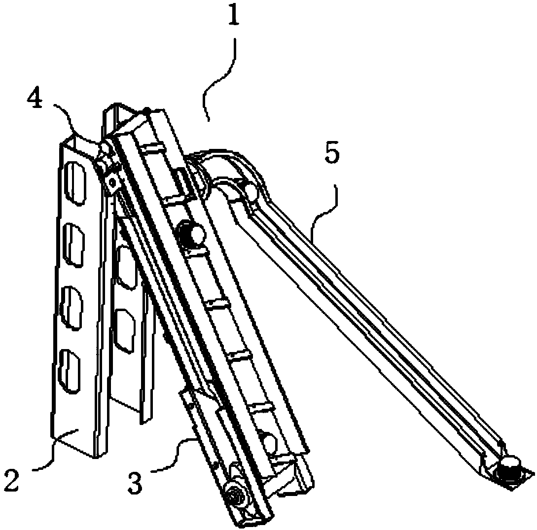
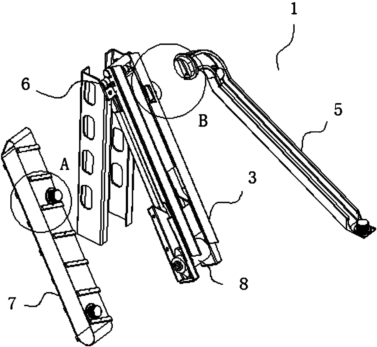
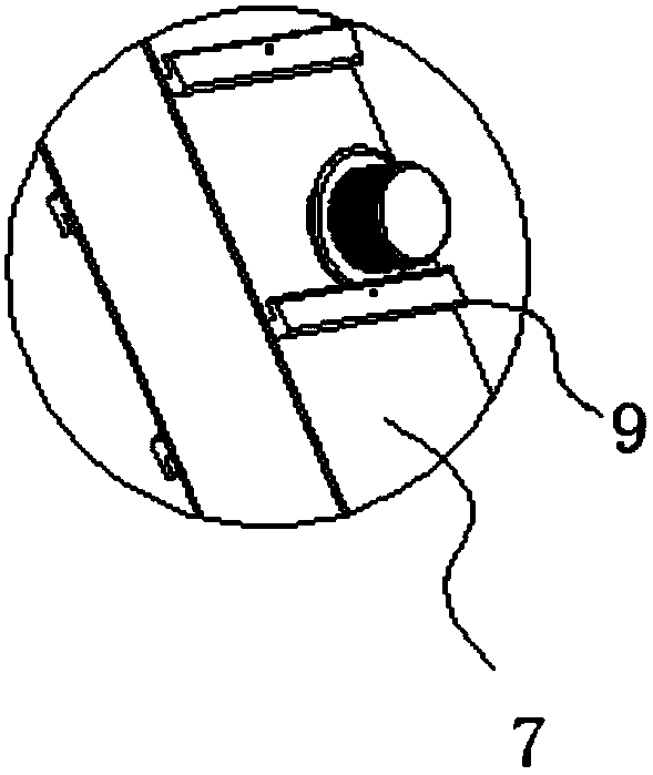
[0021] Such as Figure 1 to Figure 4 As shown, the screening device 1 includes two supporting legs 2, a conveying rack 3 is provided on one side of the supporting leg 2, a driven wheel 4 is provided on the top of the conveying rack 3, and a driving wheel 8 is provided at the bottom of the conveying rack 3. A conveyor belt 7 is installed inside the conveying rack 3, a screening hole 10 is arranged on the top side of the conveying rack 3, a connecting pipe 11 is arranged on one side of the filtering hole 10, and a discharging trough 5 is arranged on one side of the connecting pipe 11. One end of the discharging trough 5 is provided with a set of tubes 12, the middle of the sleeve 12 is provided with a discharging hole 13, the top of the driven wheel 4 is provided with a hinge 6, and the conveyor belt 7 is provided with a plurality of clamping slots 9 outside.
[0022] The driving wheel 8 is connected to the driven wheel 4 through the conveyor belt 7, and the conveyor belt 7 is movably connected with the driving wheel 8 and the driven wheel 4.
[0023] The two supporting legs 2 are arranged in parallel, and the supporting leg 2 is rotatably connected with the conveying frame 3 through the hinge 6.
[0024] The connecting pipe 11 is matched with the sleeve 12, and the connecting pipe 11 is engaged with the sleeve 12.
[0025] The card slot 9 is inclined.
[0026] Both the screening hole 10 and the discharging hole 13 have a square structure, and the screening hole 10 is connected to the discharging tank 5 through the discharging hole 13.
[0027] The top of the discharging trough 5 has a circular arc structure.
[0028] When used, such as figure 1 , figure 2 , image 3 with Figure 4 As shown, the user directly engages the gear parts that need to be screened into the slot 9, and the gear parts can move on the inclined slot 9 so that the gear parts are close to the side wall of the feeder 3, and the conveyor belt 7 places the gear The parts are conveyed to the top of the feeding rack 3. When the slot 9 where the gear parts are placed corresponds to the screening hole 10, the gear parts that meet the specifications slide out from the screening hole 10 and flow to the discharge slot 5 through the discharge hole 13. Slide to the bottom of the discharging trough 5 for collection. The gear parts larger than the screen hole 10 are conveyed to the top of the conveyor 3 by the conveyor belt 7 and slide down on the side of the support leg 2 for collection. The conveyor 3 is supported by the support leg 2. Makes the structure of the conveying rack 3 stable. When the user needs to adjust the angle of the conveying rack 3, the hinge 6 on the top of the support leg 2 is used to rotate the conveying rack 3 to adjust the angle so that the sleeve 12 can be removed from the connecting pipe. 11 is removed from the top to disassemble the discharging slot 5, which is convenient to use.
[0029] The use of the card slot 9 enables the conveyor belt 7 to transport gear parts through the card slot 9, and the gear parts can also slide through the card slot 9, thereby making the screening work more convenient, more efficient, and effective.
[0030] The screening device has simple structure, obvious effect, low cost and strong practicability.
[0031] It is not limited to this, and any changes or replacements that are not thought of through creative work shall be covered by the protection scope of the present invention. Therefore, the protection scope of the present invention should be subject to the protection scope defined by the claims.

PUM

no PUM

Description & Claims & Application Information

We can also present the details of the Description, Claims and Application information to help users get a comprehensive understanding of the technical details of the patent, such as background art, summary of invention, brief description of drawings, description of embodiments, and other original content. On the other hand, users can also determine the specific scope of protection of the technology through the list of claims; as well as understand the changes in the life cycle of the technology with the presentation of the patent timeline. Login to view more.

Similar technology patents

Anticoagulation coating material and preparation method thereof

InactiveCN103721300Ahigh anticoagulant activitystable structure
Owner:HUAZHONG UNIV OF SCI & TECH

High temperature-resistant and high-insulation sealing glass and preparation method thereof

ActiveCN105776868AImprove glass fluiditystable structure
Owner:XIAN SEAL ELECTRONICS MATERIAL TECH CO LTD

Mechanical arm for plate installing

Owner:阜阳市润泰通用机械有限公司

Classification and recommendation of technical efficacy words

  • stable structure
  • easy to use

Silicon/carbon composite microsphere negative electrode material as well as preparation method and application for same

ActiveCN103311522Astable structureImprove charge and discharge cycle life
Owner:INST OF PROCESS ENG CHINESE ACAD OF SCI

Preparation method of magnetic graphene based oil absorption foam material

Owner:XINJIANG TECHN INST OF PHYSICS & CHEM CHINESE ACAD OF SCI
Why Eureka
Try Eureka