Swing-amplitude-adjustable baby hammock

An adjustable swing amplitude technology, which is applied in the field of baby hammocks, can solve problems such as the inability to control the swing amplitude of the hammock, and achieve the effect of sleeping comfortably and reducing the burden

Active Publication Date: 2018-09-14
章雪霞
View PDF6 Cites 13 Cited by
  • Summary
  • Abstract
  • Description
  • Claims
  • Application Information

AI Technical Summary

Problems solved by technology

But this device can't control the swing of the hammock

Method used


Image

  • Swing-amplitude-adjustable baby hammock
  • Swing-amplitude-adjustable baby hammock
  • Swing-amplitude-adjustable baby hammock

Examples


specific Embodiment approach 1

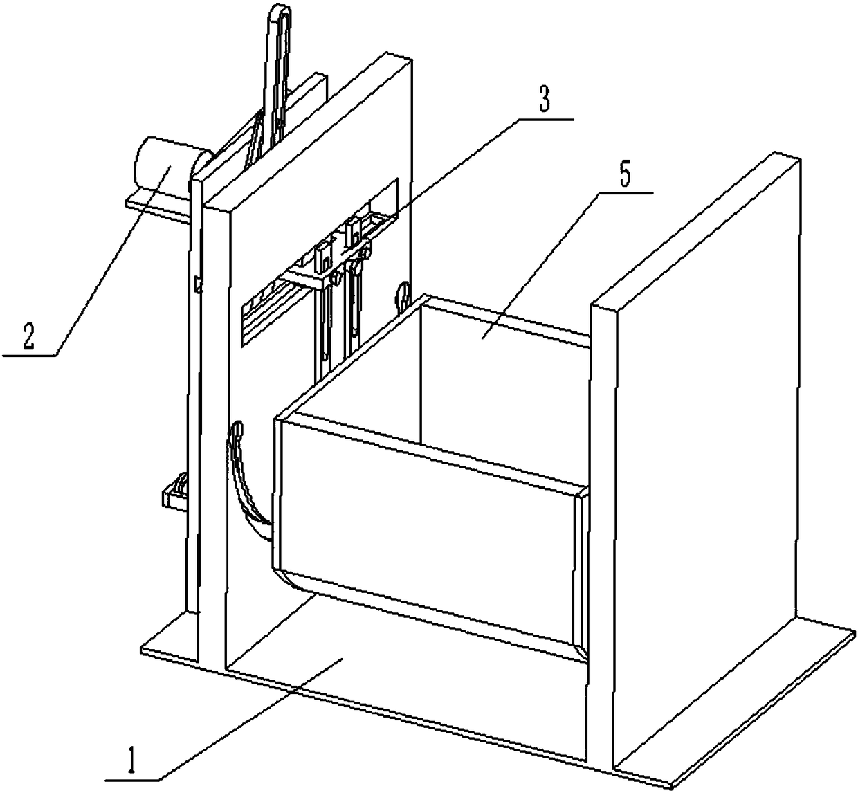
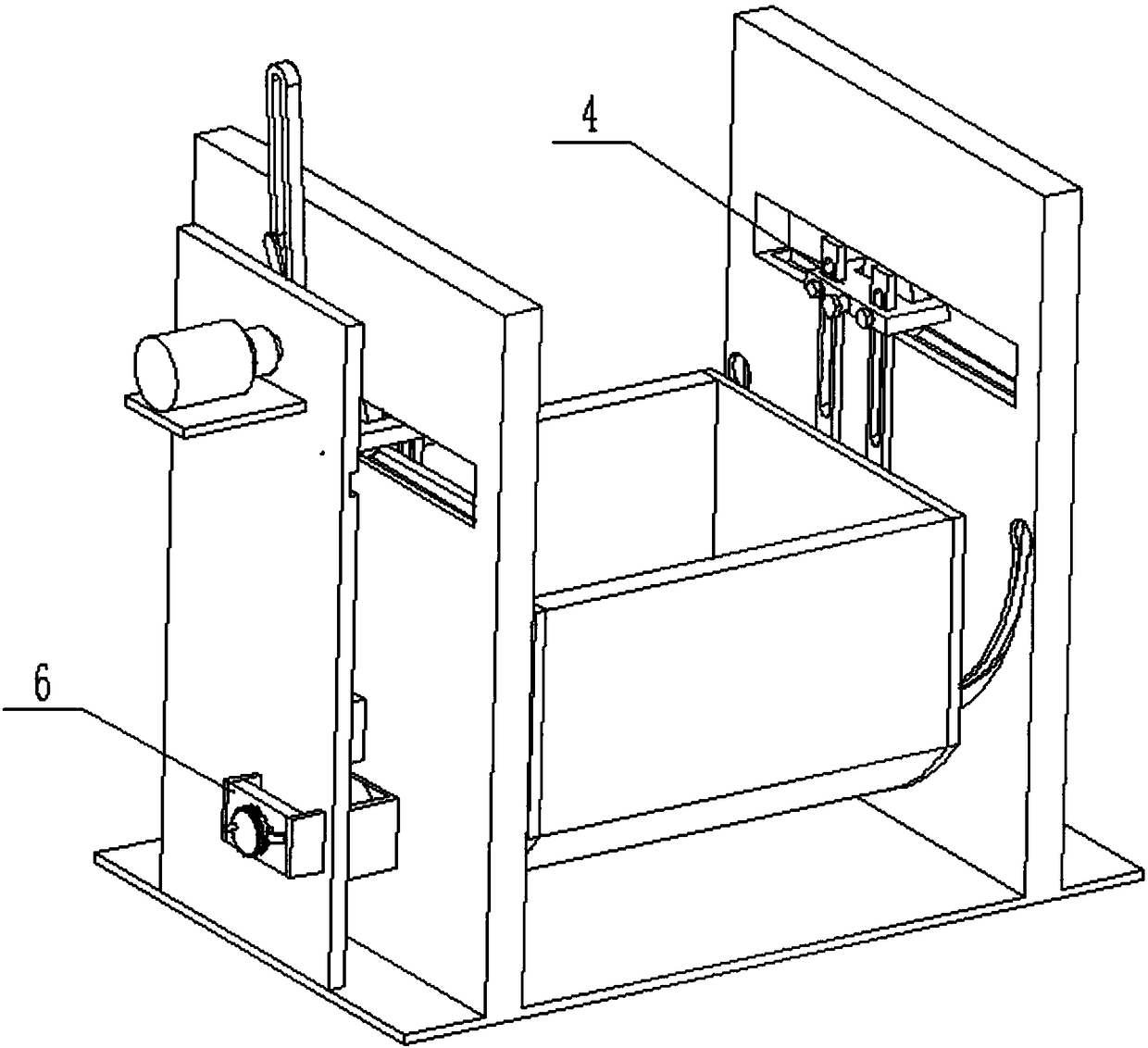
[0025] Such as Figure 1 to Figure 9 As shown, a baby hammock with adjustable swing range includes a base 1, a transmission adjustment structure 2, a main transmission structure 3, a driven structure 4, a baby hammock 5, a protection structure 6 and a driving slider 7. The transmission The adjustment structure 2 is fixedly connected to the left end of the base 1, and two driving sliders 7 are provided. The transmission structure 3, the transmission adjustment structure 2 is slidably connected in the two driving sliders 7, the main transmission structure 3 is slidably connected to the base 1, the right end of the main transmission structure 3 is hinged to the baby hammock 5, and the right end of the baby hammock 5 is hinged to the driven The structure 4 and the driven structure 4 are slidably connected to the base 1 , and the protection structure 6 is plugged into the left end of the base 1 . The transmission adjustment structure 2 drives the main transmission structure 3, the...

specific Embodiment approach 2

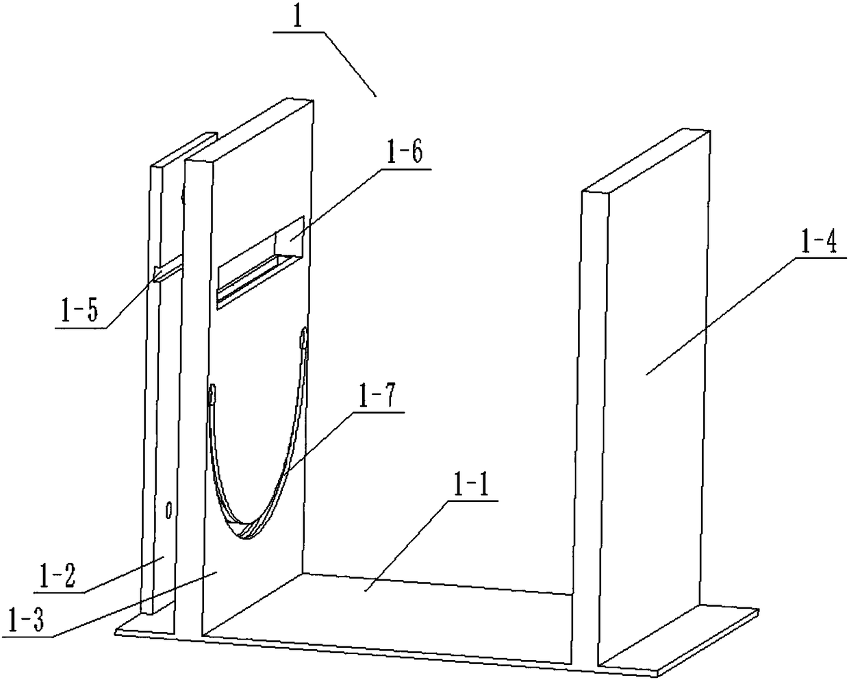
[0026] Such as Figure 1 to Figure 9 As shown, this embodiment further describes the first embodiment, the base 1 includes a bottom plate 1-1, a transmission fixing plate 1-2, a left base plate 1-3, a right base plate 1-4, a horizontal slide Slot 1-5, rectangular through slot 1-6, arc chute 1-7, rectangular slot 1-8, arc chute I 1-9, motor rotation through hole 1-10, adjustment shaft through hole 1- 11 and a rectangular slot 1-12, the transmission fixing plate 1-2 is fixedly connected to the left end of the base plate 1-1, the right base plate 1-4 is fixedly connected to the right end of the base plate 1-1, and the left base plate 1-3 is fixed Connected to the bottom plate 1-1, the left base plate 1-3 is set between the transmission fixed plate 1-2 and the right base plate 1-4, and the horizontal chute 1-5 is set at the right end of the transmission fixed plate 1-2 , the rectangular through slot 1-6 is arranged on the left base plate 1-3, the rectangular through slot 1-6 is p...

specific Embodiment approach 3

[0027] Such as Figure 1 to Figure 9As shown, this embodiment will further explain Embodiment 2. The transmission adjustment structure 2 includes a motor 2-1, a rotating rod 2-2, a driving cylinder 2-3, a driving rod 2-4, and a displacement block 2-5. , adjust the rotation groove 2-6, fixed block 2-7, displacement rack 2-8, gear 2-9, adjustment shaft 2-10, rotating toothed disc 2-11 and hand rocker 2-12, motor 2-1 Fixedly connected on the transmission fixed plate 1-2, the transmission shaft of the motor 2-1 is rotatably connected in the motor rotation through hole 1-10, the rotating rod 2-2 is fixedly connected on the transmission shaft of the motor 2-1, and drives the cylinder 2 -3 is fixedly connected to the rotating rod 2-2, the driving rod 2-4 is provided with a driving groove, the driving cylinder 2-3 is slidably connected in the driving groove of the driving rod 2-4, and the lower end of the driving rod 2-4 is hinged on On the displacement block 2-5, the displacement ra...


PUM


Abstract

The invention discloses a swing-amplitude-adjustable baby hammock which comprises a base, a transmission adjusting structure, a driving structure, a driven structure, a baby hammock body, a protectionstructure and two driving sliders. The swing-amplitude-adjustable baby hammock has the advantages that a baby bed can be automatically swung, a baby is comforted to fall asleep, the baby hammock relieves burden of an adult for soothing the baby to fall asleep, swing amplitude can be adjusted according to actual situations such as age and body weight of a baby, so that sleep of the baby is more comfortable, the transmission adjusting structure is fixedly connected at the left end of the base, left ends of the two driving sliders are slidably connected on the base, the right ends of the two driving sliders are fixedly connected with the driving structure, the transmission adjusting structure is slidably connected in the two driving sliders, the driving structure is slidably connected on thebase, the right end of the driving structure is hinged to the baby hammock, the right end of the baby hammock is hinged to the driven structure, the driven structure is slidably connected on the base, and the protection structure is inserted into the left end of the base.

Description

technical field [0001] The invention relates to the field of baby products, in particular to a baby hammock with adjustable swing range. Background technique [0002] A crib is a special bed specially designed to comfort infants and young children to sleep. Patent No. CN201410044369.2 discloses a baby cot that utilizes incomplete gears to swing bidirectionally, which includes a fixed frame at the bottom of the bed, surrounding pipes, and four foot pipes that are detachably engaged with the surrounding pipes. The top of the foot pipes is movably connected to the rocker. The two ends of the fixed frame at the bottom of the bed are riveted to two adjacent rockers along the length direction of the bed, and there are grooves on the adjacent rockers along the width direction of the bed, and the grooves are connected to the sliders on both sides of the movable rod. Cooperate, the movable rod is movably connected with the connecting block, and the connecting block is provided with ...

Claims


Application Information

Patent Timeline
Patent Type & Authority Applications(China)
IPC IPC(8): A47D9/02
CPCA47D9/02
Inventor 章雪霞
Owner 章雪霞
Why Eureka
Try Eureka