Escalator overturning-preventing floor plate

An escalator and anti-turnover technology, which is applied to escalators, transportation and packaging, etc., can solve problems such as economical, cheap and unreasonable, and achieve the effect of maintaining the anti-turnover effect, simplifying the structure, and avoiding the tripping situation

Pending Publication Date: 2018-09-14
SUZHOU LAIYIN ELEVATOR CO LTD
View PDF14 Cites 1 Cited by
  • Summary
  • Abstract
  • Description
  • Claims
  • Application Information

AI Technical Summary

Problems solved by technology

A typical one such as CN106241583B introduces "a high-safety floor slab". In this patent, a connecting block is arranged below the floor middle slab, and the connecting block is snapped and connected with the connecting plate below, and the connecting plate is fixedly connected to the truss; A fixed block is set under the middle plate, and a fixed groove is set on the side of the fixed block. A rivet is arranged under the floor rear plate, and a fixed bar that can rotate around the rivet is set on the rivet. The fixed bar matches the fixed slot (specifically, the Refer to paragraphs 0029 to 0030 of the description of the patent), this patent solution can reflect the technical effects of the three aspects summarized in paragraphs 0016 to 0018 of the description, but there are the following shortcomings: First, the patent is to make the floor board It is reliably fixed with the truss, so a connecting block is set under the mid-floor plate, which is used as a transition part between the mid-floor plate and the additional connecting plate located below the mid-floor plate, and is connected by screws passing through the mid-floor plate block and screw into the connecting plate to form a whole floor middle plate, connecting block and connecting plate, and then fix the connecting plate together with the floor middle plate and the truss of the elevator. The way of fixing the middle plate and the truss seems to be unreasonable in terms of structure simplification, resource saving, manufacturing and assembly convenience, and low cost; A connecting block is set between the additional connecting plates, and the connecting block protrudes from the surface of the connecting plate toward the side of the mid-floor plate (that is, the surface of the connecting plate facing the mid-floor plate), so that the opposite side of the mid-floor plate and the connecting plate And there is a hollow compartment formed between the areas of the non-connecting blocks. On the one hand, when stepping on the mid-floor board, it will make a sound that passengers usually do not want to hear (because the sound will arouse the fear of passengers), on the other hand, the mid-floor board The overall load-bearing capacity is weakened or even vulnerable; thirdly, because the anti-turnover structure design of the opposite side of the floor middle plate and the floor back plate is through the fixing bar and the It is reflected by the cooperation of the fixing slots on the fixing plate fixed on the middle floor of the floor (paragraph 0030 of the manual), so it does not have a buckling or matching relationship with the truss, so when passengers frequently step on the middle and rear floors of the floor During the process, there is a risk that the fixing bar will move out of the fixing groove of the fixing plate abnormally, and once the movable (pivoting) fixing bar set with the floor rear plate as the carrier and the middle floor plate as the carrier set If the fixing grooves on the fixing plate are separated (disengagement

Method used


Image

  • Escalator overturning-preventing floor plate
  • Escalator overturning-preventing floor plate

Examples


Embodiment Construction

[0021] In order to understand the technical essence and beneficial effects of the present invention more clearly, the applicant will describe in detail the following in the form of examples, but the description of the examples is not to limit the solution of the present invention. Equivalent transformations that are only formal but not substantive should be regarded as the scope of the technical solution of the present invention.

[0022] In the following descriptions, all concepts related to directionality or orientation of up, down, left, right, front and rear are based on figure 1 As far as the position state shown is concerned, it cannot be understood as a special limitation on the technical solution provided by the present invention.

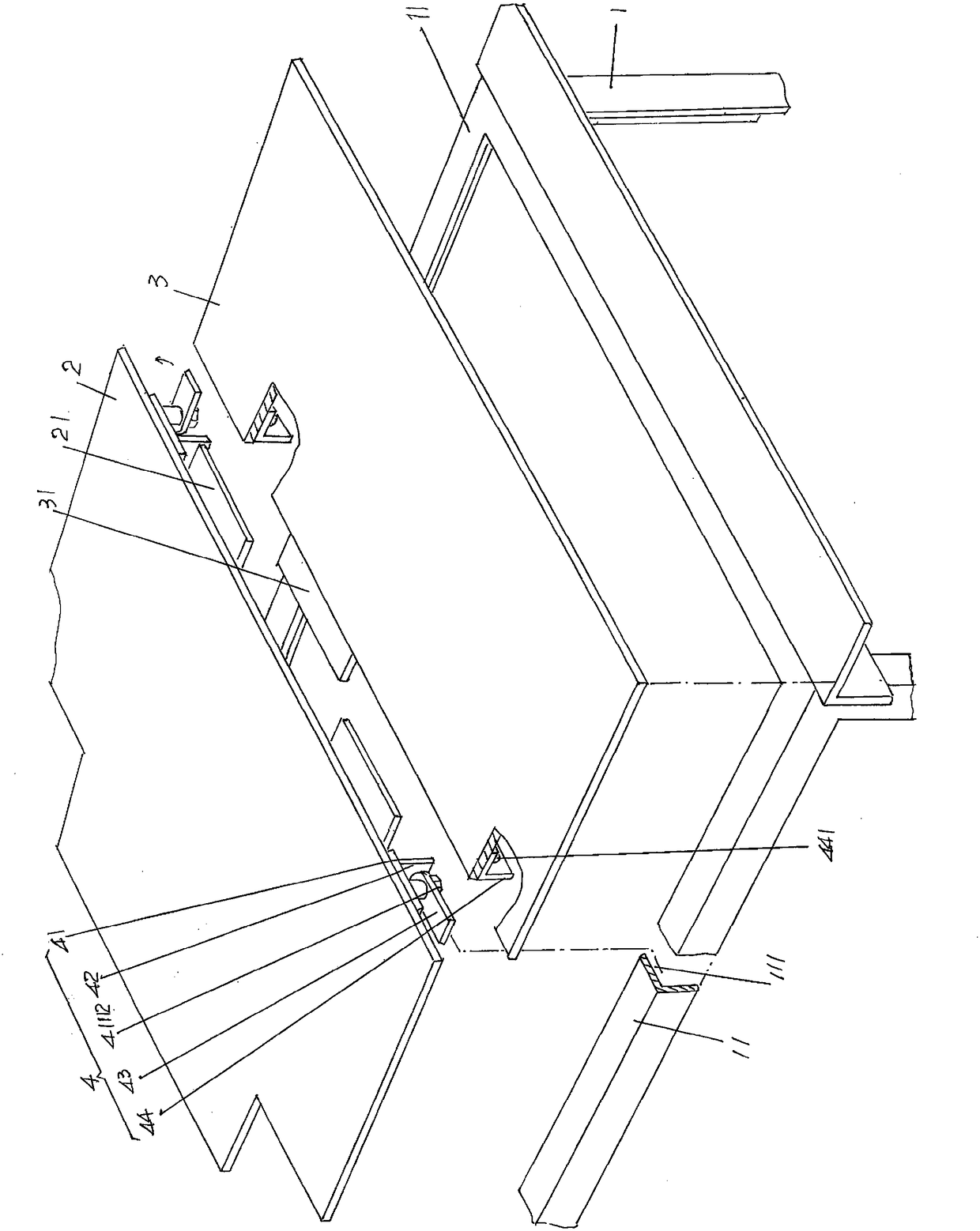
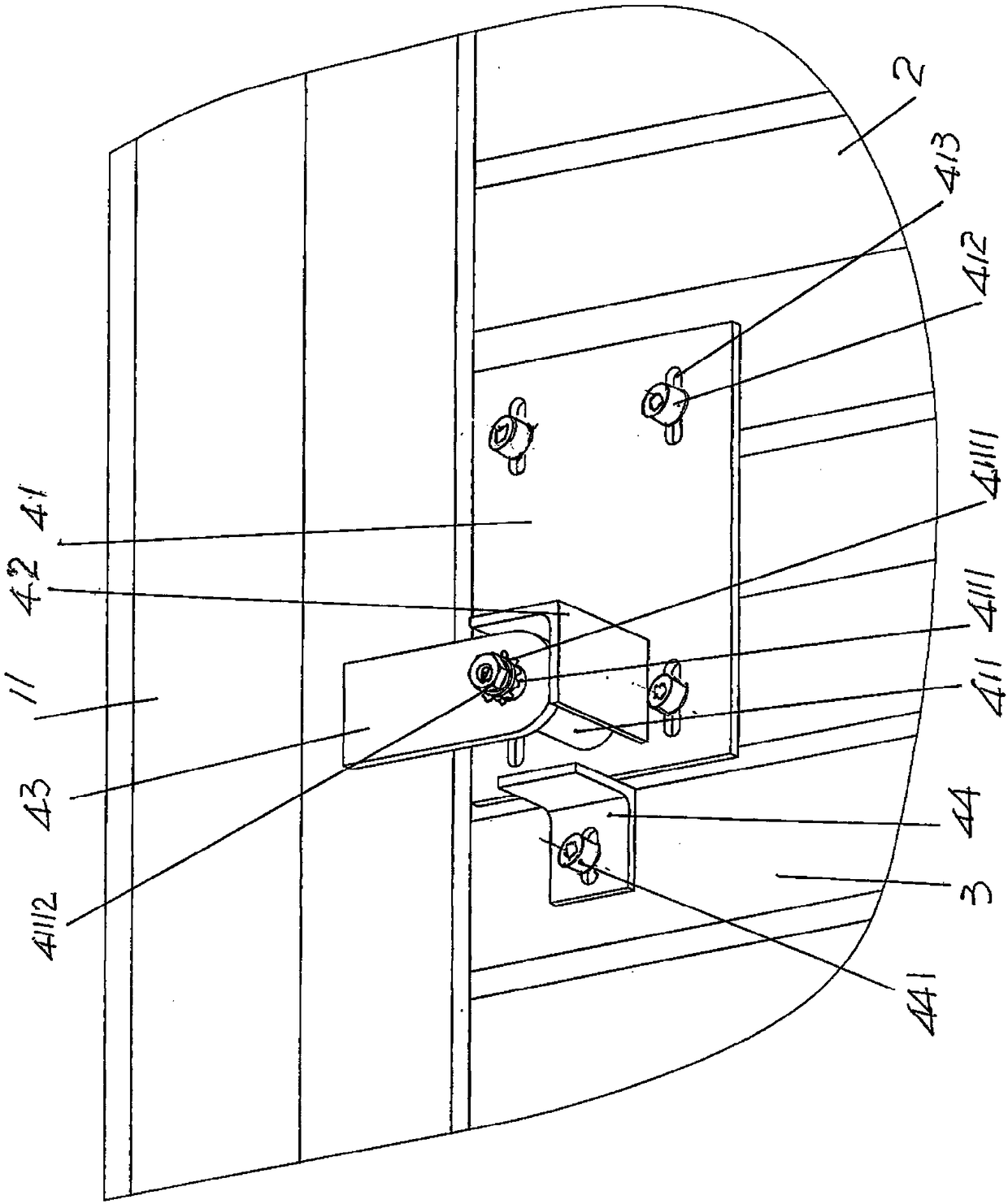
[0023] See figure 1 and figure 2, shows a truss 1 of the structural system of the escalator, and a pair of truss longitudinal beams 11 are fixed on the upper part of the truss 1 and along the length direction of the truss 1 .

[0024] B...


PUM


Abstract

The invention relates to an escalator overturning-preventing floor plate, and belongs to the technical field of escalators. An escalator comprises a truss, a pair of truss longitudinal beams are arranged at the upper portion of the truss, the overturning-preventing floor plate comprises a floor middle plate and a floor back plate, and floor middle plate overturning-preventing mechanisms are arranged below the front and back ends of the side, facing the floor back plate, of the floor middle plate. The escalator overturning-preventing floor plate is characterized in that each floor middle plateoverturning-preventing mechanism comprises a limiting corner fitting fixing plate, a limiting corner fitting, a buckling plate and a buckling plate stopping foot, wherein the limiting corner fitting fixing plate and the downward side of the floor middle plate are fixed, the limiting corner fitting fixing plate is provided with a screw shaft base, the tail end of the screw shaft base is provided with a screw shaft, the limiting corner fitting and the limiting corner fitting fixing plate are fixed, one end of the buckling plate is arranged on the screw shaft and is limited by a nut, a spring padis arranged between the nut and the buckling plate, one end of the buckling plate is buckled to the pair of truss longitudinal beams, and the buckling plate stopping foot is fixed to the downward side of the floor back plate. The structure is simplified, and manufacturing and installing are facilitated; and noise generated when the floor middle plate is stepped, and the overturning-preventing effect is kept.

Description

technical field [0001] The invention belongs to the technical field of escalators, and in particular relates to an anti-turnover floor plate of an escalator. Background technique [0002] The aforementioned floor board includes the floor mid-slab and the floor back board, that is to say, the floor board is the collective name of the floor mid-slab and the floor rear board, and the floor mid-slab is also called "front pedal", while the floor rear board is also called "back-edge pedal" , both are used simultaneously. In the state of use, the position of the middle plate of the floor is located in front of the comb plate of the escalator, that is, between the comb plate and the rear plate of the floor, and the comb plate, the middle plate of the floor and the rear plate of the floor are all arranged on the truss of the escalator on the upper pair of truss stringers. Corresponding to the machine room of the escalator in the space below the middle plate and the rear plate of th...

Claims


Application Information

Patent Timeline
Patent Type & Authority Applications(China)
IPC IPC(8): B66B23/00
CPCB66B23/00
Inventor 吴晓燕朱云飞张逢博
Owner SUZHOU LAIYIN ELEVATOR CO LTD
Why Eureka
Try Eureka