
Network province coordination new energy station dynamic reactive power reserve target allocation method

A technology of grid-province coordination and target allocation, applied in reactive power compensation, reactive power adjustment/elimination/compensation, AC network circuits, etc. capacity, the effect of stable grid-connected power generation

Active Publication Date: 2021-07-13
NARI TECH CO LTD +5
View PDF4 Cites 0 Cited by
  • Summary
  • Abstract
  • Description
  • Claims
  • Application Information

AI Technical Summary

Problems solved by technology

If the dynamic reactive power reserve target value distribution of the new energy station is unreasonable, it is likely to reduce the safe and stable operation of the new energy station.

Method used


Image

  • Network province coordination new energy station dynamic reactive power reserve target allocation method
  • Network province coordination new energy station dynamic reactive power reserve target allocation method
  • Network province coordination new energy station dynamic reactive power reserve target allocation method

Examples


Embodiment Construction

[0037] In order to make the above objects, features and advantages of the present invention more obvious and easy to understand, the following will clearly and completely describe the specific implementation of the present invention in conjunction with the accompanying drawings in the embodiments of the present invention, and the accompanying drawings of the present invention are in simplified form , is only used for the purpose of conveniently and clearly describing the embodiment of the present invention.

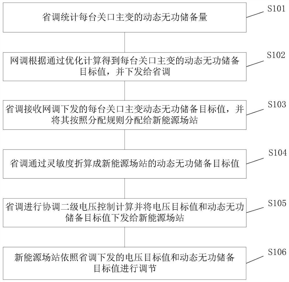
[0038] figure 1 It is a schematic flow diagram of an embodiment of the network province coordinated new energy station dynamic reactive power reserve target allocation method provided by the present invention, as shown in figure 1 shown, including steps:

[0039] S101. Provincial commissioning and statistics of the dynamic reactive power reserve of the main transformer at the provincial coordination gateway of each network.

[0040] Assuming that there are n new energy ...


PUM


Abstract

The invention discloses a method for allocating dynamic reactive power reserve targets of grid-provincial coordination new energy stations, including provincial survey and statistics of the dynamic reactive power reserve of each grid-provincial coordination gateway main transformer; The dynamic reactive power reserve target limit of the gateway main transformer is issued to the provincial dispatcher; the dynamic reactive reserve target limit of each network provincial coordination gateway main transformer issued by the provincial dispatcher is received and network dispatched, and is calculated according to the set distribution principle The upper and lower limits of the dynamic reactive power reserve target assigned to the new energy station; the AVC main station of the provincial adjustment will send the calculated target value of the bus voltage on the high voltage side of the new energy station and the upper and lower limit of the dynamic reactive power reserve target to the new energy field The AVC sub-station of the station; the AVC sub-station of the new energy station performs reactive power adjustment according to the target value of the bus voltage and the upper and lower limits of the dynamic reactive power reserve target. The method of the invention retains a reasonable dynamic reactive power reserve, improves the ability of each new energy collection area to cope with abnormal disturbances such as faults, and realizes stable grid-connected power generation of new energy.

Description

technical field [0001] The invention relates to reactive power reserve coordinated control between network dispatching and provincial dispatching, in particular to a dynamic reactive power reserve target allocation method for network-province coordinated new energy stations, which belongs to the technical field of automatic voltage control of electric power systems. Background technique [0002] In recent years, the installed capacity of new energy has continued to increase, and the proportion of new energy output to the entire network load has increased year by year. The high proportion of new energy has affected the voltage support capacity of the power grid. The large fluctuations in output have made it difficult to adjust the voltage of the power grid, and voltage problems in some areas have become prominent . The amount of reactive power reserve is strongly related to the safety and stability of the system, and its optimization is an important means to ensure the safety...

Claims


Application Information

Patent Timeline
Patent Type & Authority Patents(China)
IPC IPC(8): H02J3/18
CPCH02J3/1871Y02E40/30
Inventor 徐陆飞陈天华行舟黄华陈建华杜磊杨洛王玮付嘉渝张鹏赵德伟张宪康
Owner NARI TECH CO LTD
Learn More