
Blow moulding machine automatic replacement equipment

An automatic replacement and blow molding machine technology, applied in the field of film blowing machines, can solve problems such as energy-consuming, affect production efficiency, and high cost, and achieve the effects of saving time and financial resources, simple structure, and simple and convenient replacement

Inactive Publication Date: 2018-09-18
苏东利
View PDF0 Cites 0 Cited by
  • Summary
  • Abstract
  • Description
  • Claims
  • Application Information

AI Technical Summary

Problems solved by technology

Since the impurities in the solution will adhere to the filter, the filter needs to be replaced and cleaned after a period of use, otherwise the filter will be blocked and the solution will not be able to circulate normally
Every time the filter is replaced, it not only needs to stop the machine, but also needs at least 15 minutes to replace the filter, which affects the production efficiency and brings economic losses to the manufacturer.
[0003] There is an existing film blowing machine, which detachably sets the filter screen and automatically replaces the filter screen by means of machinery, but this device cannot replace the clamping part, and the clamping part will be worn out after a long time of use. It needs to be replaced. To replace the clamping part of this device, the whole device can only be disassembled and replaced as a set, which is very costly and labor-intensive

Method used


Image

  • Blow moulding machine automatic replacement equipment
  • Blow moulding machine automatic replacement equipment
  • Blow moulding machine automatic replacement equipment

Examples


Embodiment Construction

[0025] In order to enable those skilled in the art to better understand the solutions of the present invention, the technical solutions in the embodiments of the present invention will be clearly and completely described below in conjunction with the drawings in the embodiments of the present invention. Obviously, the described embodiments are only It is a part of embodiments of the present invention, but not all embodiments. Based on the embodiments of the present invention, all other embodiments obtained by persons of ordinary skill in the art without making creative efforts shall fall within the protection scope of the present invention.

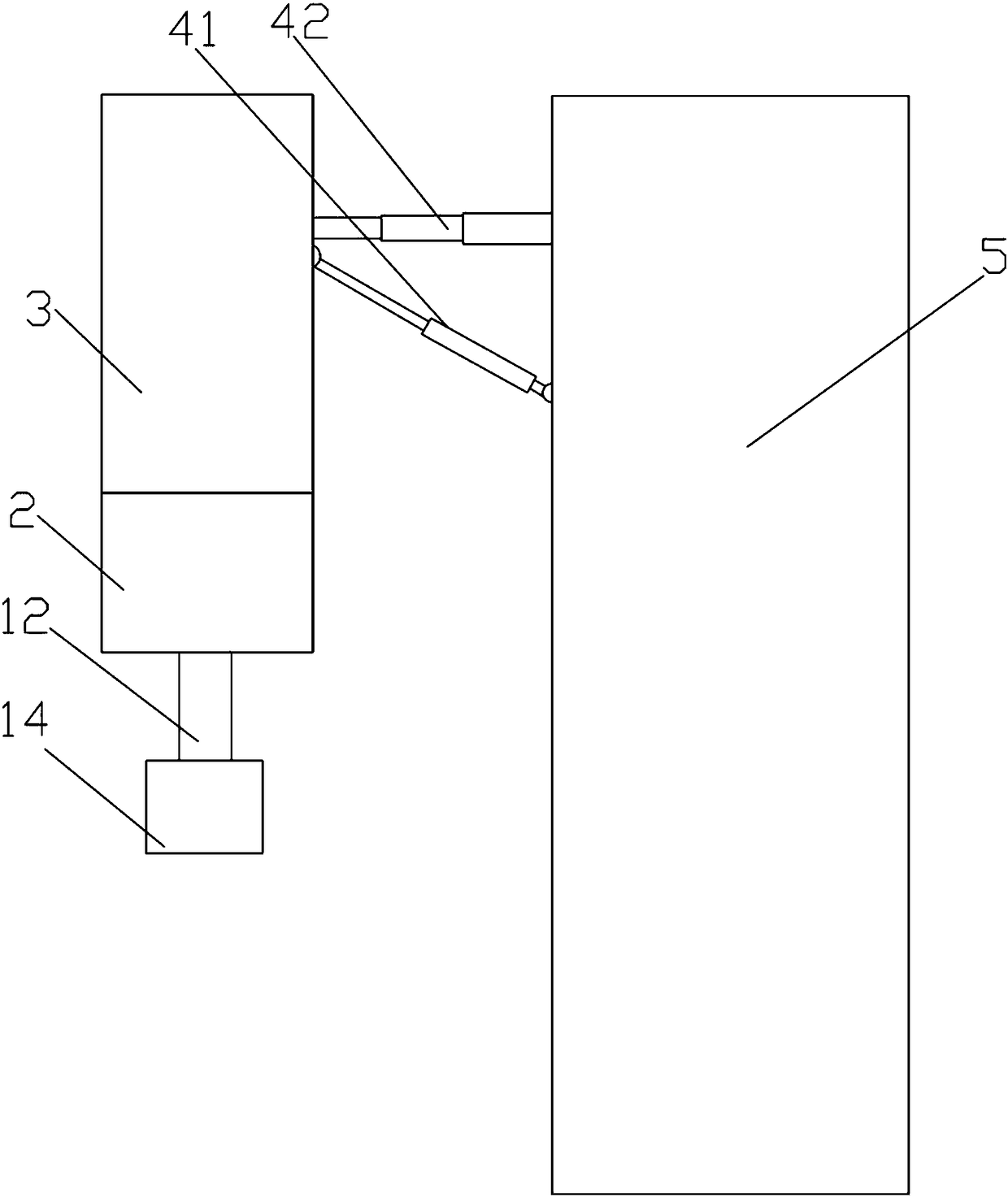
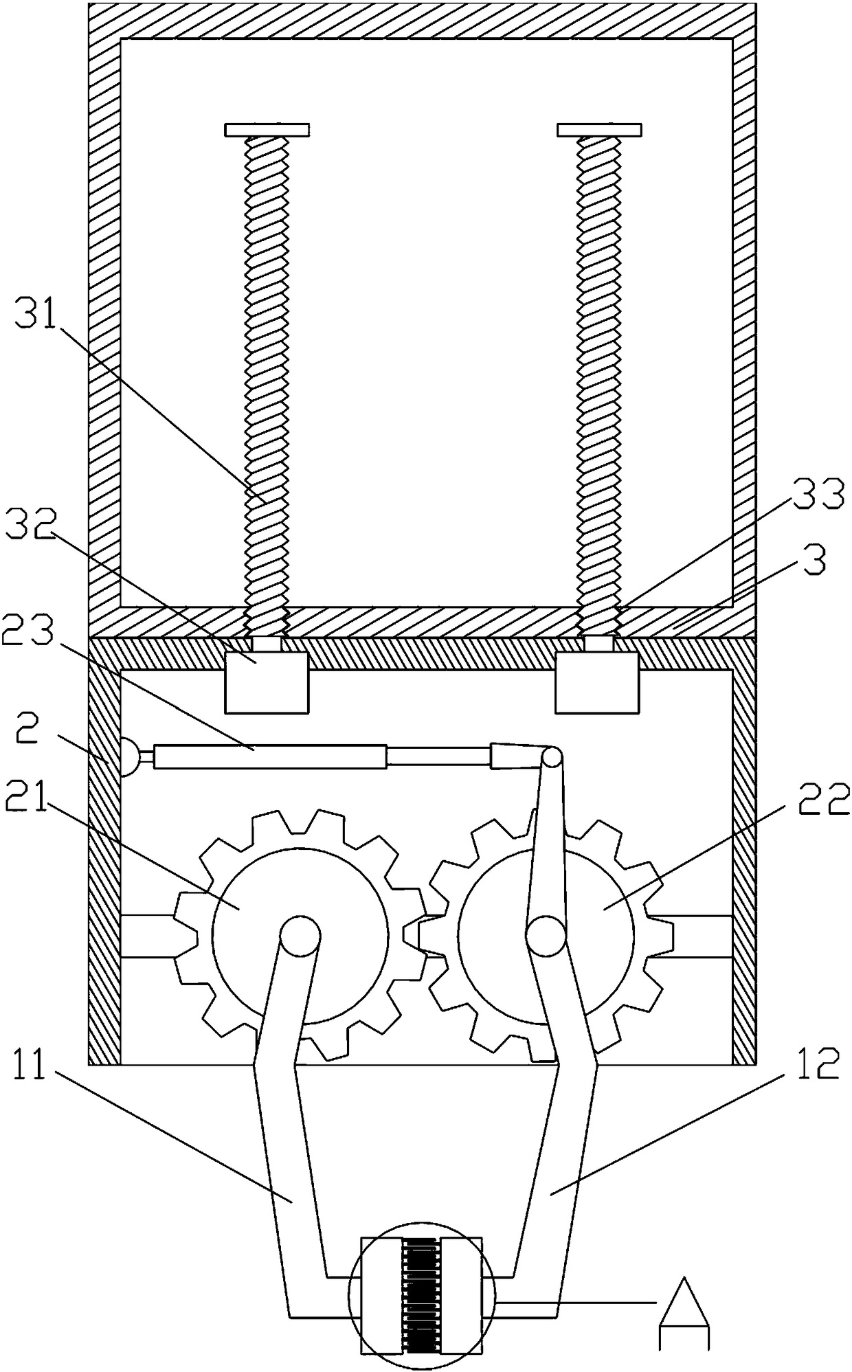
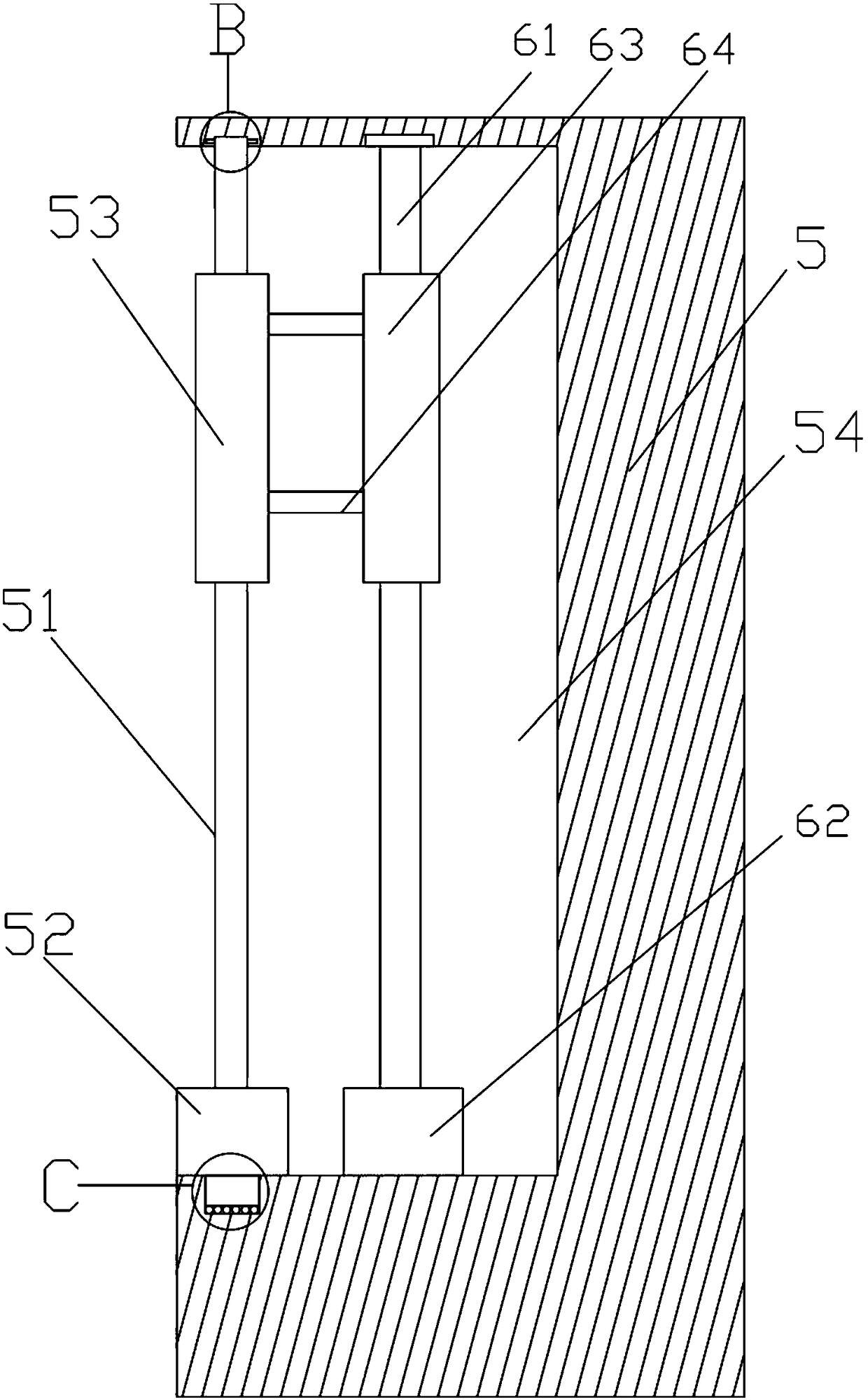
[0026] Such as figure 1- As shown, a film blowing machine filter screen replacement equipment, including a clamping mechanism, a lifting mechanism, a telescopic mechanism and a reset mechanism, the clamping mechanism is located below the lifting mechanism, the telescopic mechanism is connected to the lifting mechanism, and the The reset ...


PUM


Abstract

The invention discloses blow moulding machine automatic replacement equipment. The blow moulding machine automatic replacement equipment comprises a clamping mechanism and a resetting mechanism; the clamping mechanism comprises a first clamping force arm, a second clamping force arm, a first clamping block and a second clamping block; inserting parts are correspondingly and fixedly arranged on thefirst clamping force arm and the second clamping force arm; hollow parts fitting with the inserting parts are arranged on the first clamping block and the second clamping block correspondingly; the inserting parts can be inserted into the hollow parts; with the adoption of the hollow parts, the inserting parts can be firmly fixed to the hollow parts, so that the first clamping block is dismountably connected with the first clamping force arm, and the second clamping block is dismountably connected with the second clamping force arm; and when the first clamping block and the second clamping block are worn excessively, the first clamping block can be dismounted from the first clamping force arm through a dismountable connecting mode, the second clamping block can be dismounted from the second clamping force arm through the dismountable connecting mode, and a novel first clamping block and a novel second clamping block are mounted. With the adoption of the structure, the first clamping block and the second clamping block are very convenient to replace, and the replacement cost is reduced.

Description

technical field [0001] The invention belongs to the technical field of film blowing machines, and in particular relates to automatic replacement equipment for blowing machines. Background technique [0002] Before the blown film is formed by the blown film machine, it needs to be filtered by a filter to remove impurities and particles in the plastic solution, so that the formed film has a beautiful appearance. Because the impurities in the solution will adhere to the filter screen, the filter screen needs to be replaced and cleaned after a period of use, otherwise the filter screen holes will be blocked and the solution will not be able to circulate normally. Not only does it need to stop the machine every time the filter is replaced, but it also takes at least 15 minutes to replace the filter, which affects production efficiency and brings economic losses to the manufacturer. [0003] There is an existing film blowing machine, which detachably sets the filter screen and au...

Claims


Application Information

Patent Timeline
Patent Type & Authority Applications(China)
IPC IPC(8): B29C49/42B29B13/10
CPCB29C49/4205B29B13/10
Inventor 苏东利
Owner 苏东利
Learn More