An agricultural machinery control valve

A control valve and control valve technology for agricultural machinery, applied in the field of hydraulic pressure, can solve the problems of high labor intensity, reduced work efficiency, and inability to realize simultaneous operation of the operator, so as to achieve the effect of easy and convenient lifting and steering of agricultural machinery, and improve work efficiency

Active Publication Date: 2017-02-22
ZHEJIANG HAIHONG HYDRAULIC TECH
View PDF12 Cites 1 Cited by
  • Summary
  • Abstract
  • Description
  • Claims
  • Application Information

AI Technical Summary

Problems solved by technology

The existing agricultural machinery control methods mainly control the lifting action of the actuator and the steering action of the agricultural machinery through complex linkages, and the labor intensity of the operator is relatively high.
Moreover, this control method cannot realize two kinds of actions at the same time, and cannot well adapt to the land environment of our country, and the work efficiency is greatly reduced.
With the development of hydraulic control technology, there is also the use of hydraulic system to independently control the lifting action of the actuator and the steering action of agricultural machinery. However, this control method is still relatively complicated, and through manual operation, the continuity of the two actions is difficult to guarantee.

Method used


Image

  • An agricultural machinery control valve
  • An agricultural machinery control valve
  • An agricultural machinery control valve

Examples


Embodiment Construction

[0032] The following are specific embodiments of the present invention and in conjunction with the accompanying drawings, further describe the technical solution of the present invention, but the present invention is not limited to these embodiments.

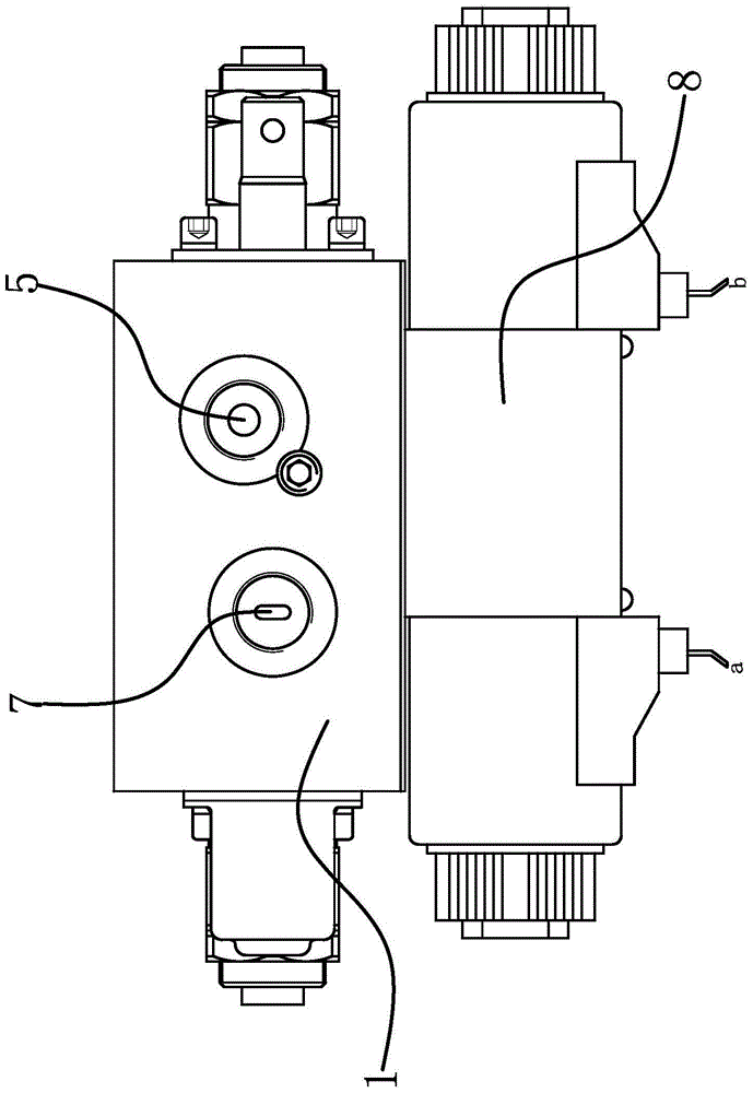
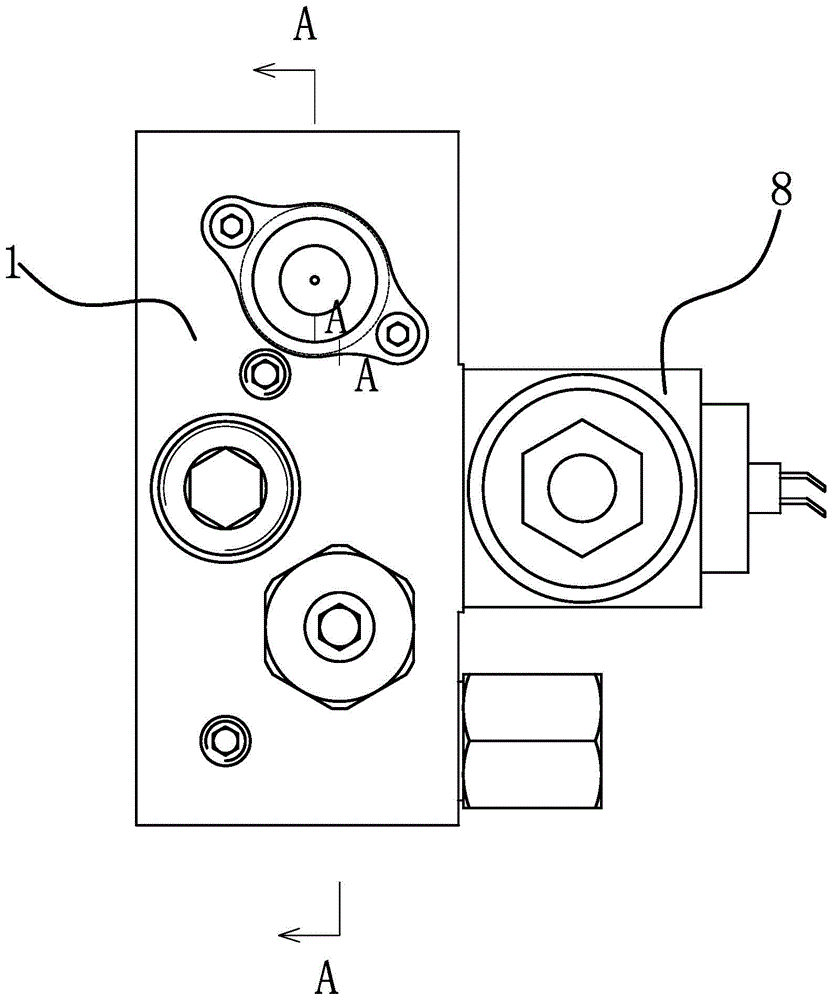
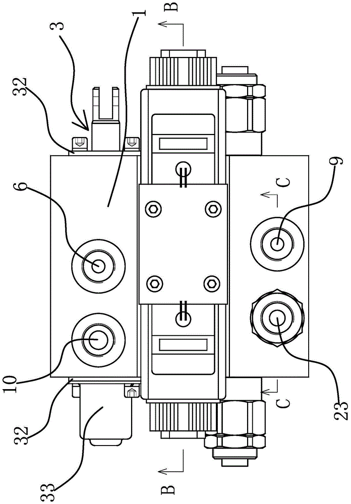
[0033] This agricultural machinery control valve is applied to agricultural machinery to realize the compound action control of the lifting action of the agricultural machinery actuator and the steering action of the agricultural machinery. header. The agricultural machinery control valve includes valve body 1, oil inlet 9, oil return port 10, steering control valve chamber 2, steering valve stem 3, steering oil inlet 4, left steering oil port 5, right steering oil port 6, steering oil return Port 7 and three-position four-way M-type solenoid valve 8.

[0034] Specifically, as figure 2 and Figure 4 As shown, the steering control valve cavity 2 is located in the valve body 1, and the steering control valve cavity 2 is respec...


PUM


Abstract

The invention provides an agriculture machine control valve, and belongs to the technical field of hydraulics. The agriculture machine control valve solves the problem that the rising and falling movement of an existing agricultural machine execution mechanism and the steering movement of an agricultural machine are not convenient to control. The agriculture machine control valve comprises a valve body and a steering control valve cavity located in the valve body. A steering valve rod is arranged in the steering control valve cavity and slides along the steering control valve cavity so that a steering oil inlet can be selectively communicated with a left steering oil opening, a right steering oil opening and a steering oil return opening. The control valve further comprises a three-position four-way M type electromagnetic valve. An oil inlet and an oil outlet are formed in the valve body. An electromagnetic valve port A and an electromagnetic valve port B of the three-position four-way M type electromagnetic valve are connected with an execution mechanism to drive the execution mechanism to rise and fall. An electromagnetic valve port P of the three-position four-way M type electromagnetic valve is communicated with the oil inlet. An electromagnetic valve port T of the three-position four-way M type electromagnetic valve is connected with the steering oil inlet. A first oil inlet passageway and a second oil inlet passageway are connected through a throttling passageway. The steering control valve cavity is connected with an oil return opening through oil return passageways. By means of the agriculture machine control valve, the work efficiency of the agricultural machine under a complex geomorphological environment is improved.

Description

technical field [0001] The invention belongs to the technical field of hydraulic pressure and relates to an agricultural machinery control valve. Background technique [0002] Agricultural machinery refers to various machinery used in crop planting and animal husbandry production, as well as in the primary processing and handling of agricultural and animal products. The agricultural machinery used in the crop planting industry can be divided into farming machinery, planting machinery and harvesting machinery according to their functions. The most typical of the farming machinery is the rotary tiller, and the most typical of the harvesting machinery is the combine harvester. [0003] With the development of industry, the degree of automation of agricultural machinery such as rotary tillers and combine harvesters in developed countries has reached a relatively high level, greatly improving agricultural productivity. Compared with developed countries in Europe and the United S...

Claims


Application Information

Patent Timeline
Patent Type & Authority Patents(China)
IPC IPC(8): F15B13/02A01B69/00
CPCA01B69/00F15B13/02F15B2013/0412
Inventor 何贤剑陈净生呼延宏高振家綦剑杨济铭孙寅虎陈善民
Owner ZHEJIANG HAIHONG HYDRAULIC TECH
Why Eureka
Try Eureka