[0027] The technical solutions in the embodiments of the present invention will be clearly and completely described below in conjunction with the accompanying drawings in the embodiments of the present invention. Obviously, the described embodiments are only a part of the embodiments of the present invention, rather than all the embodiments. Based on the embodiments of the present invention, all other embodiments obtained by those of ordinary skill in the art without creative work shall fall within the protection scope of the present invention.
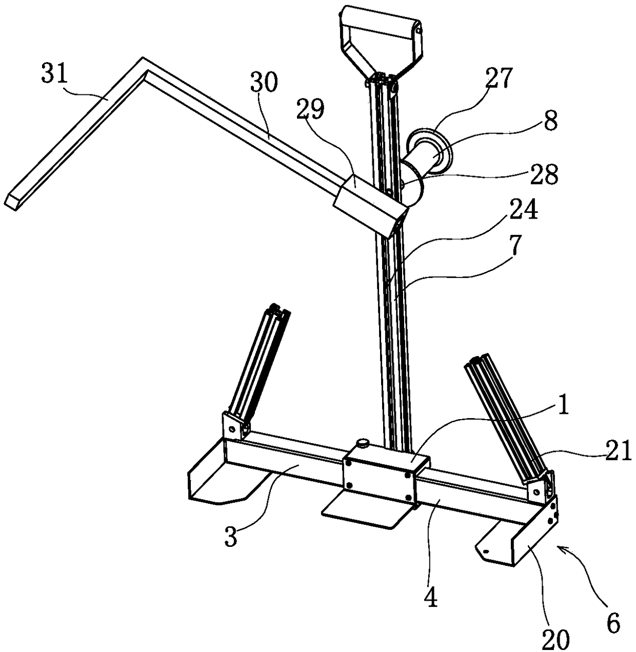
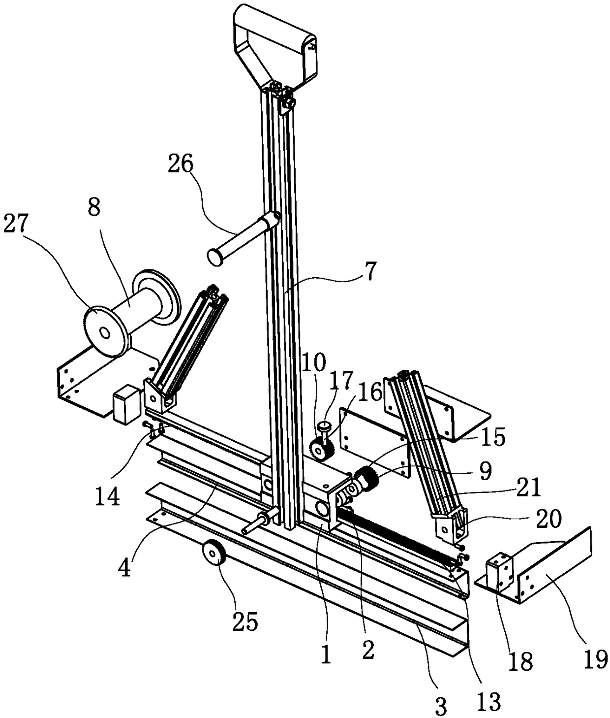
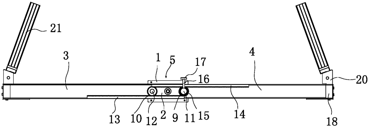
[0028] Such as Figure 1-2 As shown, the booster device for carrying the box body upstairs includes a fixed block 1. The fixed block 1 is horizontally provided with a transmission groove 2 penetrating the two side end surfaces of the fixed block 1. The transmission groove 2 is slidably connected with a first telescopic The rod 3 and the second telescopic rod 4, and the first telescopic rod 3 is sleeved on the second telescopic rod 4, the transmission groove 2 is provided with a limit transmission mechanism 5, the first telescopic rod 3 and the second telescopic rod The end of the telescopic rod 4 away from the fixed block 1 is provided with a clamping device 6, the fixed block 1 is also provided with an upright rod 7, and a booster roller 8 is detachably connected to the upright rod 7.
[0029] When the box needs to be moved upstairs, estimate the width of the box and pull the first telescopic rod 3 or the second telescopic rod 4, so that the clamping device 6 can hold a larger size than the width of the box, and it will need to be moved upstairs The box is placed in the clamping device 6, and the first telescopic rod 3 or the second telescopic rod 4 is pushed, so that the clamping device 6 clamps the box. Put the booster roller 8 on the handrail of the stairs, with the support of the handrail of the stairs, offset part of the gravity of the box body. The handrails of the stairs and people bear the gravity of G/2, and people don't have to bear the moment of heavy objects. Therefore, when using our device, it can save at least half of the effort compared with conventional transportation methods. Pushing the box body or the upright 7 makes the booster roller 8 move upward along the handrail of the stairs to carry the box body upstairs.
[0030] Preferably, the clamping device 6 includes a connecting block 18, which is fixedly connected to the end of the first telescopic rod 3 or the second telescopic rod 4 away from the fixed block 1, and the connecting block 18 is fixedly connected with a stopper. Plate 19, the baffle 19 is provided with a side stop and a lower stop, and the side stop and the lower stop are arranged vertically. The clamping device 6 further includes a turning base 20, and a gear lever 21 is rotatably connected to the turning base 20.
[0031] The side rails of the two baffles 19 are clamped on the two side walls of the box body respectively to prevent the box body from moving along the first telescopic rod 3 direction, and the stop rod 21 abuts against the box wall of the box body to prevent the box body Flip to the direction away from the operator to limit the freedom of the box, so that the box is placed on the baffle 19 smoothly. The operator can adjust the inclination angle of the gear lever 21 by rotating the turning base 20 as the rotation center according to the height of the box body, so as to optimize the clamping effect of the clamping device 6.
[0032] Preferably, the clip protection device 6 is provided with an adjustable length strap. When carrying the box upstairs, the operator should carry the strap on the shoulder and use the shoulder as the force-receiving part to improve manpower conversion and reduce labor intensity. As we all know, the strength of the human shoulder is much greater than the strength of the arm, and the shoulder bearing gravity is easier than the arm bearing gravity, which enhances the user experience of the invention.
[0033] Preferably, a support plate is provided on the fixed block 1 to further limit the freedom of the box body and make the transportation more stable.
[0034] Preferably, as Figure 3-4 As shown, the limit transmission mechanism 5 includes a first gear 9 and a second gear 10. The first gear 9 is provided with a first gear shaft 11, and the second gear 10 is provided with a second gear shaft 12 , The first gear shaft 11 and the second gear shaft 12 are arranged in parallel, the first gear shaft 11 is rotatably connected with the fixed block 1, and the second gear shaft 12 is fixedly connected with the fixed block 1. The limit transmission mechanism 5 also includes a first rack 13 and a second rack 14. The first rack 13 is fixedly mounted on the first telescopic rod 3, and the second rack 14 is connected to the first rack. 13 is arranged opposite to the second telescopic rod 4, the first rack 13 is meshed and connected with the first gear 9 and the second gear 10, and the second rack 14 is connected with the first gear 9 and the second gear, respectively. The gear 10 is meshed and connected to realize the linkage of the first telescopic rod 3 and the second telescopic rod 4.
[0035] After the box is placed, preferably the first telescopic rod 3 is pushed, the first rack 13 drives the first gear 9 and the second gear 10 to rotate, and the first gear 9 and the second gear 10 drive the second telescopic rod 4 along the A telescopic rod 3 moves in the opposite direction, and the first telescopic rod 3 and the second telescopic rod 4 simultaneously drive the clamping device 6 arranged on the first telescopic rod 3 and the second telescopic rod 4 to move the clamp in the direction close to the box body. Tighten the box. The modulus of the first rack 13 and the second rack 14 are equal, so that the first telescopic rod 3 and the second telescopic rod 4 move in an equal distance while simultaneously moving. When the clamping device 6 clamps the box, due to the action of the rack and pinion, the extension rods on both sides move synchronously, ensuring that the two extension rods are symmetrical with respect to the vertical rod in the middle, and the center of gravity of the box is projected on the two The middle of the clamping device 6 prevents the box body from shaking and turning over due to the unstable center of gravity during the transportation process.
[0036] The first gear 9 drives the first rack 13 and the second rack 14, the second gear 10 assists, and prevents the first gear 9 from driving the first rack 13 and the second rack 14, the first rack 13 and The rotation of the second rack 14 makes the movement of the first rack 13 and the second rack 14 more stable. When clamping the box, the first gear 9 and the second gear 10 are the two supporting points of the first rack 13 and the second rack 14 to prevent the first rack 13 and the second rack 14 from rotating.
[0037] Preferably, a one-way bearing 15 is provided between the first gear 9 and the first gear shaft 11, and the inner and outer rings of the one-way bearing 15 are fixedly connected to the first gear shaft 11 and the first gear 9 respectively, The second gear 10 and the second gear shaft 12 are rotatably connected. The first gear shaft 11 is provided with a positioning screw 16. One end of the positioning screw 16 abuts on the first gear shaft 11, and the other end protrudes from the fixed block 1 and is provided with a knurled stigma 17. The positioning screw 16 Screw on the fixed block 1.
[0038] When the distance between the two clamping devices 6 is to be adjusted, the knurled column head 17 is rotated so that the end of the positioning screw 16 close to the first gear shaft 11 is separated from the first gear shaft 11, and the first gear shaft can be rotated. The telescopic rod 3 and the second telescopic rod 4 can be freely synchronized telescopically. Pull the first telescopic rod 3 or the second telescopic rod 4 to adjust the distance between the two clamping devices 6. After the adjustment is completed, the knurled stigma 17 rotates the positioning screw 16 to abut the first gear shaft 11 to limit the first gear The shaft 11 rotates. After placing the box, push the first telescopic rod 3 or the second telescopic rod 4 so that the clamping device 6 is close to the side wall of the box. At this time, since the first gear shaft 11 is locked, the ratchet mechanism in the one-way bearing 15 makes The first gear 9 can only drive the first telescopic rod 3 or the second telescopic rod 4 to contract, so that the clamping device 6 hugs the box body. No other positioning mechanism is required to limit the position of the clamping device 6, and the operation is simple and fast. ,
[0039] Preferably, as Image 6 As shown, the side of the fixed block 1 is provided with a first limiting slot 22 perpendicular to the transmission slot 2 and a second limiting slot 23 parallel to the transmission slot 2, and the vertical rod 7 is clamped in the first limiting slot. 22 or the second limiting slot 23. The fixing block 1 is screwed with a bolt 32, and one end of the bolt 32 away from the fixing block 1 is fixedly provided with a pressing plate 25, and the pressing plate 25 is pressed on the vertical rod 7.
[0040] When it is necessary to use this box to carry the booster device upstairs, rotate the vertical rod 7 and clamp the vertical rod 7 into the first limit slot 22, and the rotating compression plate 25 is pressed against the vertical rod 7 by the bolt 32, so that the vertical rod 7 is fixed on the In the first limiting slot 22. After using the box to carry the booster device upstairs, loosen the compression plate 5, take the pole 7 out of the first limit slot 22, rotate the screw to the position of the second limit slot 23, and The vertical rod 7 is clamped into the second limiting groove 23, and then the vertical rod 7 is pressed by rotating the compression plate 25. The upright rod 7 is parallel to the first telescopic rod 3, which reduces the space and volume of the booster device for carrying the box body upstairs and is convenient for users to carry.
[0041] Further, an adjusting groove 24 is provided on the vertical rod 7, and the bolt 32 is inserted through the adjusting groove 24. The height of the stair handrail is different. According to the height of the stair handrail, the height of the adjusting bolt 32 in the adjusting groove 24 is adjusted to change the distance between the fixed block 1 and the booster roller 8. The box body moving upstairs assist device can adapt to more stair handrail heights, and the universality of the box body moving upstairs assist device is improved.
[0042] Preferably, the booster roller 8 is arranged on the side of the vertical pole away from the fixed block 1, the booster roller 8 is rotatably connected with a roller shaft 26, and the roller shaft 26 is fixedly connected to the vertical rod 7. Such as image 3 As shown, the two ends of the booster roller 8 are provided with a finite clamping edge 27, and a sleeve 28 sleeved on the roller shaft 26 is provided between the booster roller 8 and the vertical rod 7. When the box is transported, the booster roller 8 is rotated by the forward thrust, turning sliding friction into rolling friction, reducing frictional resistance, and further reducing labor intensity. In order to protect the surface of the stair handrail, it is preferable to use materials such as nylon for the booster roller. The limit card edge 27 effectively prevents the booster roller 8 from leaving the handrails of the stairs in the process of carrying the box body, and improves the safety performance of the booster device for carrying the box body upstairs. Such as Figure 5 As shown, the assisting roller 8 can smoothly pass through the corner of the stair handrail to realize the function of continuously going upstairs.
[0043] Preferably, a handle 28 is provided at one end of the upright rod 7 away from the fixed block 1, and a fixed sleeve 29 is also provided on the upright rod 7, and the fixed sleeve 29 is detachably connected to the upright rod 7. An extension rod 30 is inserted into the fixing sleeve 29. The extension rod 30 is arranged obliquely, and an end of the extension rod 30 away from the fixing sleeve 29 is provided with an armrest rod 31 extending in a direction away from the booster roller 8. When transporting small boxes, the fixing sleeve 29, the extension rod 20 and the armrest rod 31 are removed, and the handle 28 is pushed so that the booster device for carrying the box upstairs has upward power. When the height of the box body is higher than the height of the handle, the operator cannot hold the handle. At this time, the operator pushes the armrest rod 31 to make the box body move upstairs booster with upward power. At the same time, it prevents the box body and the box body moving upstairs booster from tipping, and increases the stability of the box body moving upstairs booster device.
[0044] The specific embodiments described herein are merely examples to illustrate the spirit of the present invention. Those skilled in the art to which the present invention pertains can make various modifications or additions to the specific embodiments described or use similar alternatives, but they will not deviate from the spirit of the present invention or exceed the definition of the appended claims. Range.
[0045] Although this article mostly uses the fixed block 1, the transmission groove 2, the first telescopic rod 3, the second telescopic rod 4, the limit transmission mechanism 5, the clamping device 6, the vertical rod 7, the booster roller 8, the first gear 9. , The second gear 10, the first gear shaft 11, the second gear shaft 12, the first rack 13, the second rack 14, the one-way bearing 15, the set screw 16, the knurled stigma 17, the connecting block 18, the baffle 19. Flip seat 20, gear lever 21, first limit slot 22, second limit slot 23, adjustment slot 24, compression plate 25, roller shaft 26, limit card edge 27, shaft sleeve 28, fixed sleeve 29 , Extension rod 30, armrest rod 31. Terms, but does not exclude the possibility of using other terms. These terms are used only to describe and explain the essence of the present invention more conveniently; to interpret them as any additional limitation is contrary to the spirit of the present invention.