
Rotatably-fixed-type anterior cervical spine zero-incisura interbody fusion cage

An intervertebral fusion device and anterior cervical fusion technology, which is applied in the field of rotating and fixed anterior cervical zero-notch intervertebral fusion, can solve the problems of product fusion, loosening, prolapse, etc. Income, reduce the effect of resection

Active Publication Date: 2018-09-28
RESEARCH INSTITUTE OF TSINGHUA UNIVERSITY IN SHENZHEN
View PDF2 Cites 0 Cited by
  • Summary
  • Abstract
  • Description
  • Claims
  • Application Information

AI Technical Summary

Problems solved by technology

Another object of the present invention is to provide a gap connection that not only enables the fixing plate to effectively clamp and fix the fusion body, but also ensures that the fixing plate can move and rotate within a small range relative to the fusion body. This method effectively solves the problem of When the fusion device is first implanted in the patient's body, the product cannot be fused, loosened or even prolapsed due to the movement of the patient's neck. An anterior cervical zero-profile intervertebral fusion device

Method used


Image

  • Rotatably-fixed-type anterior cervical spine zero-incisura interbody fusion cage
  • Rotatably-fixed-type anterior cervical spine zero-incisura interbody fusion cage
  • Rotatably-fixed-type anterior cervical spine zero-incisura interbody fusion cage

Examples


Embodiment Construction

[0041] The present invention will be described in further detail below in conjunction with accompanying drawing:

[0042] Figure 1 to Figure 8 A first embodiment of the invention is shown.

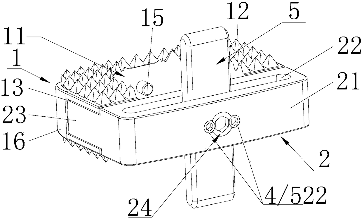
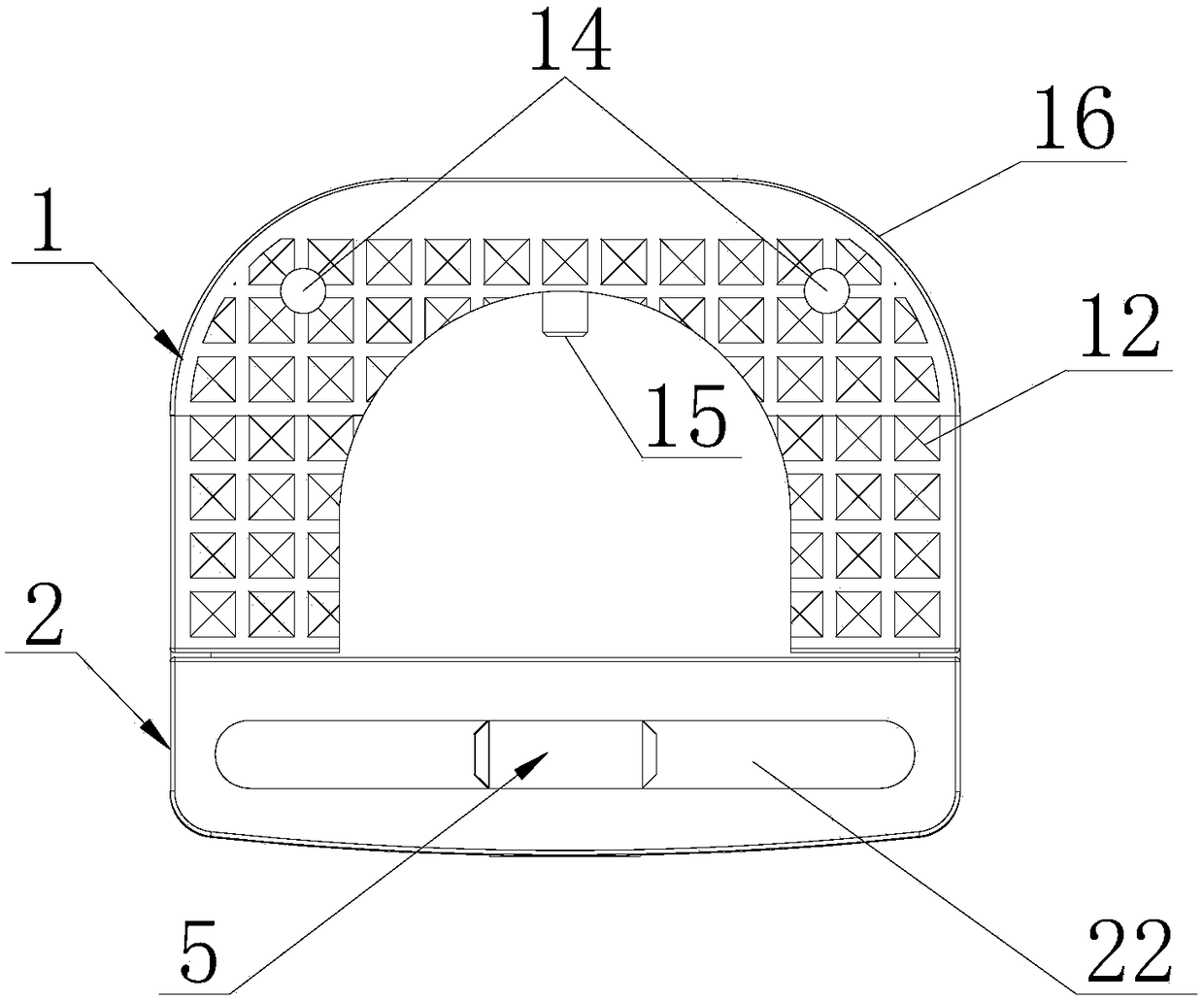
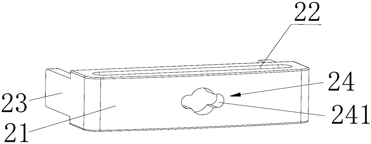
[0043] see figure 1 , figure 2 As shown, the rotation-fixed anterior cervical zero-profile intervertebral fusion cage includes a fusion cage main body 1 and a fixing member 2 that form a buckle connection with a micro-movable gap. The fuser main body 1 is composed of a U-shaped frame 11, serrations 12 protruding from the two end surfaces of the U-shaped frame 11, and an inclined chute 13 extending inwardly from the outer end wall on the outer side of the waist of the U-shaped frame 11 symmetrically; The front end of the U-shaped frame 11 of the main body of the fusion device is provided with a radius of 0.5 mm to 2 mm arc surface 16, which is convenient for prosthesis implantation, and coincides with the structure of the uncinate process at the rear of the vertebral body; the front en...


PUM


Abstract

The invention relates to a rotatably-fixed-type anterior cervical spine zero-incisura interbody fusion cage comprising a fusion cage main body and a fixing component which form micro-gap buckle connection. The fixing component is composed of a mother board, clamping arms, clamping hook parts, first rotating pin holes, rotating pins, stop screws, rotatable fixing pieces and second rotating pin holes, wherein the mother board is provided with an upper penetrating inserting groove and a lower penetrating inserting groove; the clamping arms are perpendicular to the mother board and are arranged onthe two sides of the mother board in a protruding mode and used for being inserted in inclined sliding grooves of the fusion cage main body; the clamping hook parts are arranged at the ends of the clamping arms in an inwards-perpendicularly extending mode; the first rotating pin holes perpendicularly penetrating through the inserting grooves are formed in the center of the surface of the mother board; the rotating pins are embedded in the rotating pin holes; the stop screws are in symmetrical screw joint with the interiors of the rotating pin holes; the rotatable fixing pieces are mounted inthe inserting grooves of the mother board in a sleeved mode; and the second rotating pin holes matched with the rotating pin holes are formed in the centers of the rotatable fixing pieces. The fusioncage main body is composed of a U-shaped frame, sawteeth formed in the two end faces of the U-shaped frame in a protruding mode, and the inclined sliding grooves symmetrically formed in the outer sideface of the waist of the U-shaped frame, wherein the inclined sliding grooves extend inwards from the outer end wall.

Description

technical field [0001] The invention relates to a rotation-fixed anterior cervical zero-notch intervertebral fusion device. Background technique [0002] There are already more than ten kinds of zero-profile cervical intervertebral fusion devices such as PEEK PREVAIL, Zero~P, ROI~C, MC+, COALITION, STALIF~C, etc., which have been widely used in Europe, America, Asia and other places. However, there are few self-designed zero-notch fuser products authorized in China, and most of the authorized and pending applications are changes based on the structural shape and size of foreign products, and there are few products with innovative structural designs. [0003] CN104068949.A discloses an anterior cervical zero-notch intervertebral fusion device. The structure includes: a PEEK thick-plate fusion cage and two TC4 fastening screws, and the upper and lower sides of the front of the thick-plate fusion cage are provided with limit stops , to prevent excessive implantation, the upper...

Claims


Application Information

Patent Timeline
Patent Type & Authority Applications(China)
IPC IPC(8): A61F2/44
CPCA61F2/30749A61F2/4455A61F2002/30428A61F2250/0098
Inventor 刘伟强祝佳廖振华李阳
Owner RESEARCH INSTITUTE OF TSINGHUA UNIVERSITY IN SHENZHEN
Learn More