Stamping die for special-shaped parts

A technology for stamping molds and special-shaped parts, which is applied in the field of molds, can solve problems such as cumbersome steps, and achieve the effect of increasing production speed and reducing production costs

Active Publication Date: 2018-09-28
淮安汇鸿精密模具有限公司
View PDF6 Cites 0 Cited by
  • Summary
  • Abstract
  • Description
  • Claims
  • Application Information

AI Technical Summary

Problems solved by technology

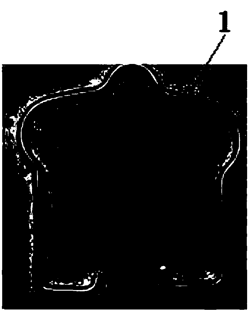
[0002] as attached figure 1 The workpiece 1 shown is a special-shaped hook. There are many production methods, and it can be made by mechanical bending. The steps are relatively cumbersome. In addition, it can also be produced by die stamping. Therefore, a stamping die suitable for the production of the workpiece is needed, which can simplify the production steps of the workpiece.

Method used


Image

  • Stamping die for special-shaped parts
  • Stamping die for special-shaped parts
  • Stamping die for special-shaped parts

Examples


Embodiment Construction

[0022] The following will be combined with Figure 1 to Figure 7 The present invention is described in detail, and the technical solutions in the embodiments of the present invention are clearly and completely described. Apparently, the described embodiments are only some of the embodiments of the present invention, not all of them. Based on the embodiments of the present invention, all other embodiments obtained by persons of ordinary skill in the art without making creative efforts belong to the protection scope of the present invention.

[0023] The following will be combined with Figure 1 to Figure 7 The present invention is described in detail, and the technical solutions in the embodiments of the present invention are clearly and completely described. Apparently, the described embodiments are only some of the embodiments of the present invention, not all of them. Based on the embodiments of the present invention, all other embodiments obtained by persons of ordinary sk...


PUM


Abstract

The invention relates to the field of dies, in particular to a stamping die for special-shaped parts. The stamping die for the special-shaped parts comprises an upper die base and a lower die base, wherein the upper die base is fixedly installed at the upper end of the lower die base; the lower end of the upper die base is provided with a connection rod and two fixing rods; the lower end of the connection rod is provided with a first upper die body fixedly connected with the connection rod; the connection rod is sleeved with a second upper die body; the lower ends of the two fixing rods are fixedly connected with the upper end of the second upper die body; a first die groove is formed in the upper end of the first upper die body; a reset assembly is arranged on the lower die base; a fixingbase is arranged at the upper end of the reset assembly; two lower die bodies are arranged at the upper end of the fixing base; linkage assemblies are arranged on the two sides of the fixing base; containing grooves are formed in the upper end of the fixing base and the end, adjacent to each other, of the two lower die bodies; and in the working state, the containing groove in the fixing base andthe containing grooves in the two lower die bodies are combined to form a second die groove. The stamping die for the special-shaped parts has the beneficial effects that workpiece can be quickly stamped and formed, the workpiece production speed is increased, and the workpiece production cost is reduced.

Description

technical field [0001] The invention relates to the field of molds, in particular to a stamping mold for special-shaped parts. Background technique [0002] as attached figure 1 The workpiece 1 shown is a special-shaped hook. There are many production methods, and it can be made by mechanical bending. The steps are relatively cumbersome, and it can also be produced by die stamping. Therefore, a stamping die suitable for the production of the workpiece is needed, which can simplify the production steps of the workpiece. Contents of the invention [0003] The purpose of the present invention is to provide a stamping die for special-shaped parts, so as to solve the problems raised in the above-mentioned background technology. [0004] The technical solution of the present invention is: comprising an upper mold base and a lower mold base, the upper mold base is fixedly installed on the upper end of the lower mold base, the lower end of the upper mold base is provided with a ...

Claims


Application Information

Patent Timeline
IPC IPC(8): B21F45/00B21F1/00
CPCB21F1/004B21F45/00
Inventor 寇雪静李德承张凯
Owner 淮安汇鸿精密模具有限公司
Why Eureka
Try Eureka